
Fire hose cleaning device

A technology for cleaning devices and fire hoses, applied to cleaning methods and tools, cleaning methods using tools, cleaning methods using liquids, etc., can solve problems such as loose fire hoses and poor cleaning effects of fire hoses, and achieve The effect of preventing wear, increasing the force bearing area, and improving cleaning efficiency

Inactive Publication Date: 2020-08-07
陶建平
View PDF1 Cites 3 Cited by
  • Summary
  • Abstract
  • Description
  • Claims
  • Application Information

AI Technical Summary

Problems solved by technology

A fire hose cleaning device in the above-mentioned patent has the following disadvantages: when the fire hose is cleaned, the fire hose may be loose due to the longer length of the fire hose, thus causing the device to damage the fire hose. The cleaning effect is poor

Method used


Image

  • Fire hose cleaning device
  • Fire hose cleaning device
  • Fire hose cleaning device

Examples


Embodiment 1

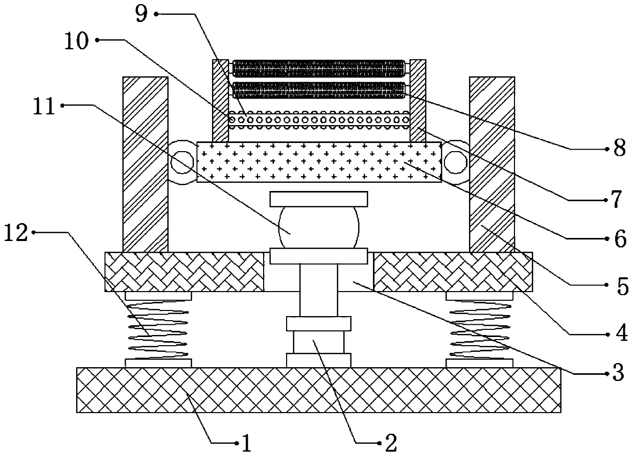
[0029] refer to Figure 1-3 , a fire hose cleaning device, comprising a fixed seat 1, one side of the top outer wall of the fixed seat 1 is connected with a cleaning box 13 by bolts, and the top outer wall of the fixed seat 1 is connected with two springs 12 by bolts, and the two springs 12 The top outer walls of the top are all connected with fixed plates 4 by bolts, the two sides of the top outer walls of the fixed plates 4 are connected with connecting plates 5 by bolts, and the opposite side outer walls of the two connecting plates 5 are connected with support plates 6 by hinges , both sides of the top outer wall of the support plate 6 are connected with fixed blocks 7 by bolts, and two support rods 9 are connected by bolts between the outer walls of the opposite side of the two fixed blocks 7, and the outer walls of the two support rods 9 are A ball groove is provided, and the inner wall of the ball groove is rollingly connected with balls 10, and the outer walls of the o...

Embodiment 2

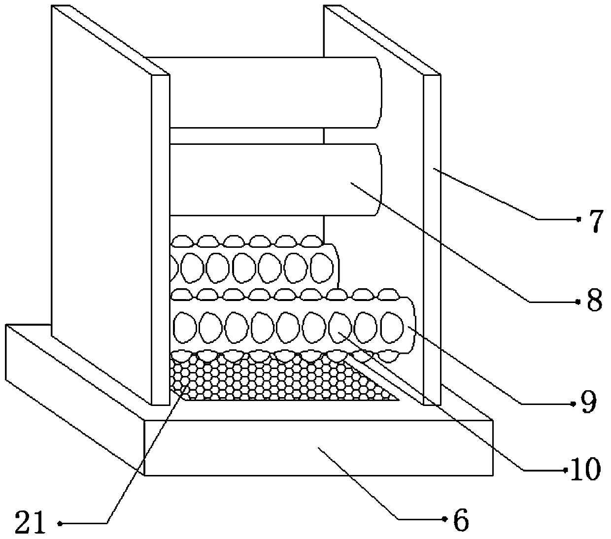
[0039] refer to Figure 4 , a fire hose cleaning device. Compared with Embodiment 1, the top outer wall of the support plate 6 is connected with a diverter plate 22 by bolts, and the outer walls on both sides of the diverter plate 22 are provided with a plurality of diversion grooves 23 .

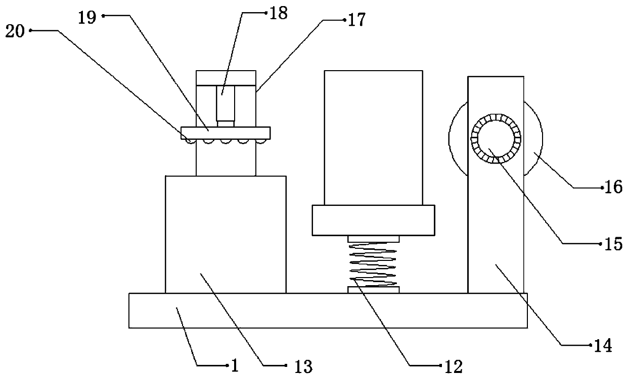
[0040] Working principle: When in use, one end of the fire hose that needs to be cleaned is wound on the surface of the winding roller 16 through the cleaning box 13, the support rod 9, the cleaning roller 8 and the support rod 9, and the motor 15 is started, and the motor 15 will drive the fire fighting machine. During the winding of the hose, the hydraulic rod 18 is activated, and the hydraulic rod 18 will drive the pressure plate 19 to move downward, so that the fire hose is immersed in the cleaning box 13 through the pressure plate 19, so as to effectively clean the fire hose , to prevent the fire hose from floating on the water surface due to the large buoyancy, which will affect the ...


PUM


Abstract

The invention discloses a fire hose cleaning device. The device comprises a fixing base, a cleaning box is fixedly connected to one side of the outer wall of the top of the fixing base, two springs are fixedly connected to the outer wall of the top of the fixing base, fixing plates are fixedly connected to the outer walls of the tops of the two springs, connecting plates are fixedly connected to the two sides of the outer walls of the tops of the fixing plates; supporting plates are connected between the outer walls of the opposite sides of the two connecting plates through hinges, fixing blocks are fixedly connected to the two sides of the outer walls of the tops of the supporting plates, and two supporting rods are fixedly connected between the outer walls of the opposite sides of the two fixing blocks. The fire hose cleaning device can prevent the surface of a fire hose from being abraded, the cleaning efficiency of the device can be improved, the situation that the cleaning effectof the fire hose is affected due to the fact that the fire hose floats on the water surface due to large buoyancy can be prevented, and stains can be prevented from dripping onto the surface of the device to cause secondary pollution to the fire hose.

Description

technical field [0001] The invention relates to the technical field of fire hoses, in particular to a cleaning device for fire hoses. Background technique [0002] Fire hoses are hoses used to transport flame-retardant liquids such as high-pressure water or foam. At present, most fire hoses are used in fire-fighting facilities, which will greatly improve the safety of fire-fighting work, but fire-fighting After the hose is used for a long time, the surface of the hose will be covered with dust and sludge, so that it is inconvenient to clean. [0003] After retrieval, the Chinese patent authorization number is CN208927494U, which discloses a fire hose cleaning device, which relates to the technical field of fire auxiliary equipment. The fire hose cleaning device includes a support platform, two support legs are fixedly installed at both ends of the bottom surface of the support platform, and a water storage tank is fixedly installed at the left end of the top surface of the ...

Claims


Application Information

Patent Timeline
IPC IPC(8): B08B3/10B08B7/02B08B13/00B08B1/02
CPCB08B3/10B08B7/02B08B13/00B08B3/041B08B1/20
Inventor 陶建平
Owner 陶建平
Features
  • Generate Ideas
  • Intellectual Property
  • Life Sciences
  • Materials
  • Tech Scout
  • Unparalleled Data Quality
  • Higher Quality Content
  • 60% Fewer Hallucinations
Learn More