Device and method for calibrating zero positions of continuous casting-and-rolling high-speed flying shear rotating drum and equipment

A technology of continuous casting and rolling, zero calibration, applied in turning equipment, auxiliary equipment, metal processing equipment, etc., can solve the problems of continuous cutting of strip steel, stacking steel, and lying billet of casting machine

Active Publication Date: 2020-08-07
SHOUGANG JINGTANG IRON & STEEL CO LTD
View PDF15 Cites 0 Cited by
  • Summary
  • Abstract
  • Description
  • Claims
  • Application Information

AI Technical Summary

Problems solved by technology

[0004] The invention provides a continuous casting and rolling high-speed flying shear drum zero calibration device and method and its equipment, which are used to solve the errors in the prior art due to the offline zero calibration of the drum, and the offline, turning, and turning of the drum. Due to the change of zero position angle during the reassembly process, the actual coincidence degree of the shear blades is reduced and the shearing conditions are not met, resulting in major accidents such as continuous cutting of strip steel, stacking of steel, and lying billets of the casting machine.

Method used


Image

  • Device and method for calibrating zero positions of continuous casting-and-rolling high-speed flying shear rotating drum and equipment
  • Device and method for calibrating zero positions of continuous casting-and-rolling high-speed flying shear rotating drum and equipment
  • Device and method for calibrating zero positions of continuous casting-and-rolling high-speed flying shear rotating drum and equipment

Examples


Embodiment 1

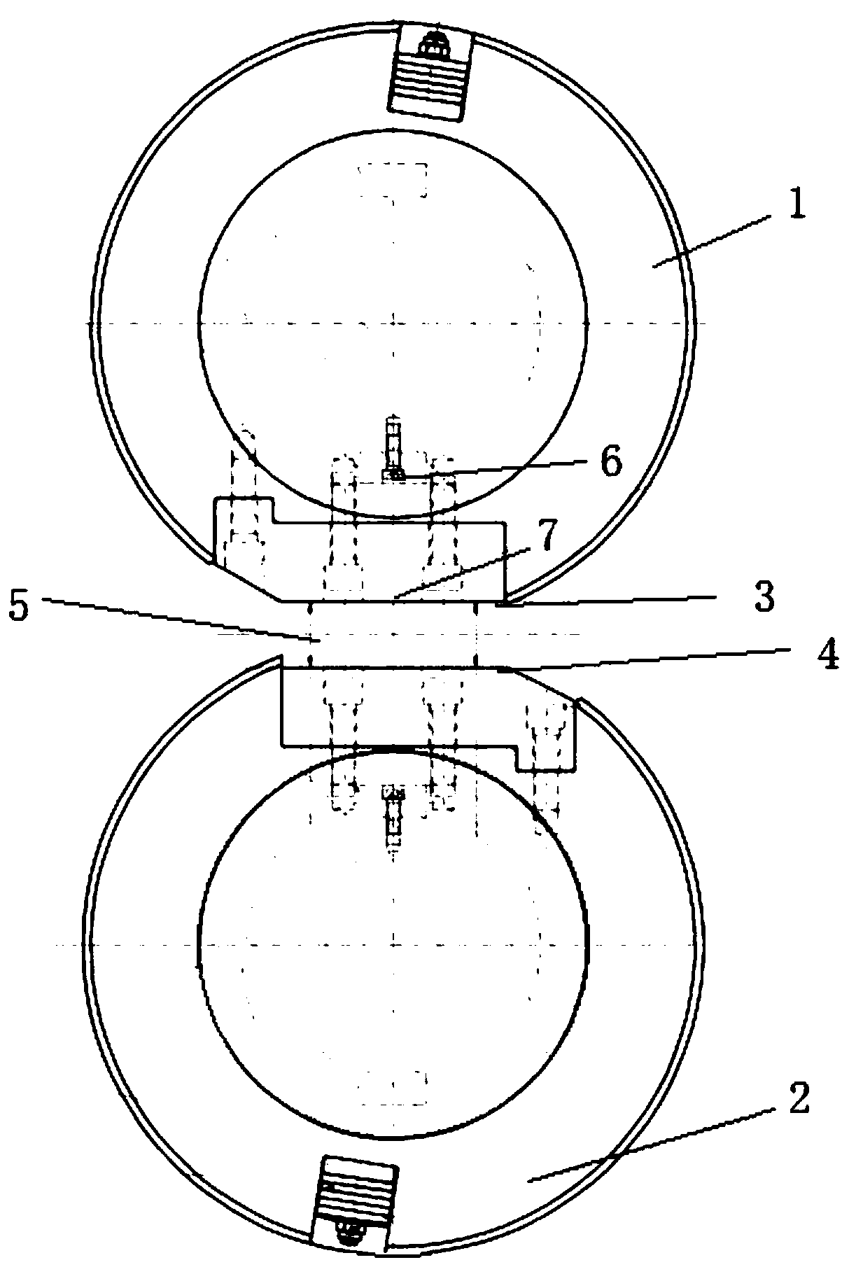
[0031] figure 1 It is a structural schematic diagram of a continuous casting and rolling high-speed flying shear drum zero calibration device in an embodiment of the present invention, as shown in figure 1As shown, a continuous casting and rolling high-speed flying shear drum zero calibration device, said device includes: a first drum 1, a second drum 2, a first horizontal plane 3, a second horizontal plane 4, and a calibration block.

[0032] The first drum 1 has a first zero position; the second drum 2 is arranged opposite to the first drum 1 and located below the first drum 1 , and the second drum 2 has a second zero position, said first zero position and said second zero position being on the same line.

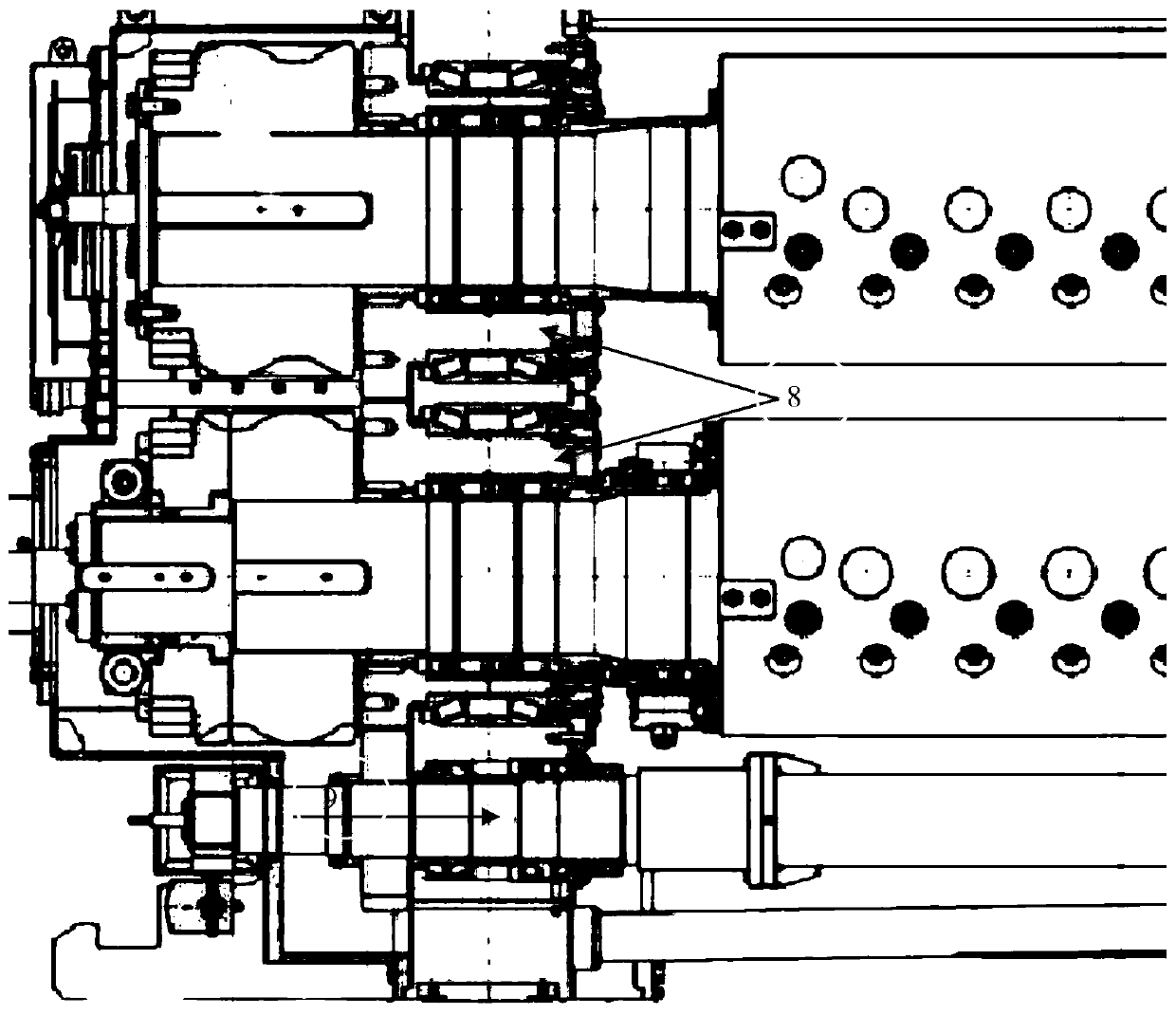
[0033] Further, the first drum 1 and the second drum 2 have the same structure, and both the first drum 1 and the second drum 2 include: a drum, an eccentric sleeve 8, a gear, and the drum has a rotating Drum zero position 6; the eccentric sleeve is arranged outside the...

Embodiment 2

[0047] A continuous casting and rolling high-speed flying shear equipment according to an embodiment of the present invention, including the continuous casting and rolling high-speed flying shear drum zero calibration device in the first embodiment, various variations and specific embodiments in the foregoing first embodiment A kind of continuous casting and rolling high-speed flying shear equipment that is also applicable to this embodiment, through the foregoing detailed description of a continuous casting and rolling high-speed flying shear drum zero calibration device, those skilled in the art can clearly know that this embodiment An implementation method of continuous casting and rolling high-speed flying shear equipment in the example.

Embodiment 3

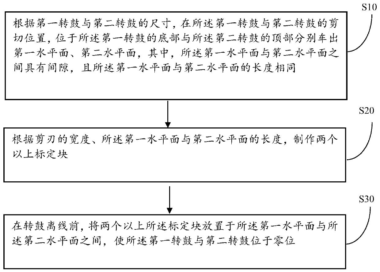
[0049] A method for calibrating the zero position of the high-speed flying shear drum for continuous casting and rolling in the embodiment of the present invention is applied to the zero position calibrating device for the high-speed flying shear drum for continuous casting and rolling in the first embodiment and the one in the second embodiment Continuous casting and rolling high-speed flying shear equipment, image 3 It is a schematic flow chart of a method for calibrating the zero position of a continuous casting and rolling high-speed flying shear drum according to an embodiment of the present invention, please refer to image 3 , the method includes:

[0050] Step 10: According to the size of the first drum 1 and the second drum 2, at the shearing position of the first drum 1 and the second drum 2, at the bottom of the first drum 1 and the second drum 2 The top of the drum 2 is driven out of the first horizontal plane 3 and the second horizontal plane 4 respectively, whe...


PUM


Abstract

The invention discloses a device and method for calibrating zero positions of a continuous casting-and-rolling high-speed flying shear rotating drum and equipment. A first rotating drum, a second rotating drum, a first horizontal plane, a second horizontal plane and a calibration block are included, the rotating drum is provided with the first zero position; the second rotating drum is arranged opposite to the first rotating drum, is located below the first rotating drum and is provided with the second zero position, and the first zero position and the second zero position are located on the same straight line; the first horizontal plane is arranged at the bottom of the first rotating drum, the second horizontal plane is arranged at the top of the second rotating drum, and a gap is arranged between the first horizontal plane and the second horizontal plane. When the device is in a shearing state, the gap is a zero gap, and the calibration block is arranged in the gap between he first horizontal plane and the second horizontal plane. The technical problem that the actual coincidence degree of a shearing blade is reduced and can not meet the shearing condition due to the error of theoffline zero position calibration of the rotating drums and the change of the zero position angle is solved. The technical effect of eliminating the error of the offline zero position calibration ofthe rotating drums, improving the accuracy of the zero position, ensuring the shearing conditions, ensuring production and improving the efficiency are achieved.

Description

technical field [0001] The invention relates to the technical field of zero-position calibration of a high-speed flying shear drum in a continuous casting and rolling line, in particular to a device and method for zero-position calibration of a high-speed flying shear drum in continuous casting and rolling and equipment thereof. Background technique [0002] The high-speed flying shear of the MCCR continuous casting and rolling line of the iron and steel company is the key equipment in the full endless rolling production mode, because the shearing action is jointly controlled by two independent movements of the high-speed flying of the drum and the variable speed rotation of the eccentric sleeve of the drum. A movement cycle of the eccentric sleeve of the drum includes motions such as static-acceleration-constant speed-acceleration-deceleration-static, etc., and the condition to ensure the smooth cutting of the strip is to ensure that the rotating The drum and drum eccentric...

Claims


Application Information

Patent Timeline
Patent Type & Authority Applications(China)
IPC IPC(8): B23B25/06
CPCB23B25/06
Inventor 彭铁龙刘冀川陈辉刘涛姜南王仁立常彦民赵坤鹏韩军亮雷振尧高利军赵俊领
Owner SHOUGANG JINGTANG IRON & STEEL CO LTD
Why Eureka
Try Eureka