
Material dipping machine for matchstick processing

A dipping and matching technology, which is applied in the field of dipping machines for match processing, can solve the problems of not being able to scrape the medicinal material smoothly, easily sore hands affect work efficiency, and it is difficult to evenly dip the matchstick, so as to avoid the movement of the scraper.

Active Publication Date: 2020-08-07
临沂高新人才教育发展集团有限公司
View PDF6 Cites 1 Cited by
  • Summary
  • Abstract
  • Description
  • Claims
  • Application Information

AI Technical Summary

Problems solved by technology

[0004] In order to overcome the shortcomings of needing to move the tools manually to scrape the medicinal materials evenly, the hands are prone to soreness and affect the work efficiency, and the dipping is done by the machine, and the medicinal materials cannot be scraped flat, which makes it difficult to evenly dip the matchsticks. The technical problem is: to provide a A kind of dipping machine for match processing that can replace manual scraping and leveling the medicinal material, avoid hand soreness affecting work efficiency, and make the match sticks evenly dipped

Method used


Image

  • Material dipping machine for matchstick processing
  • Material dipping machine for matchstick processing
  • Material dipping machine for matchstick processing

Examples


Embodiment 1

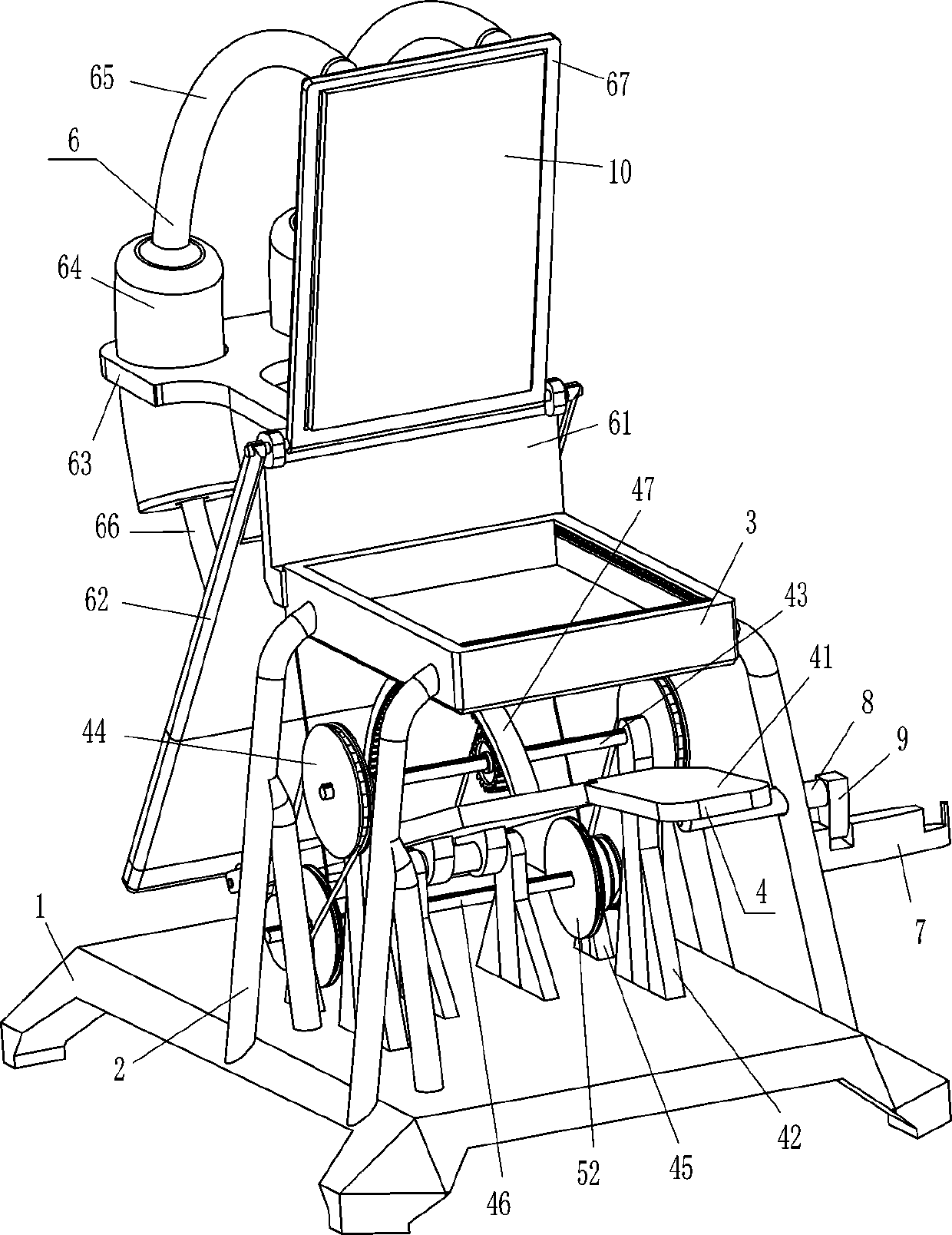
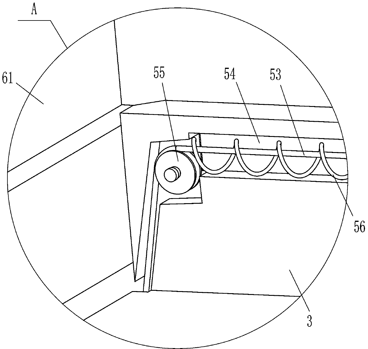
[0022] see Figure 1-Figure 3 , a dipping machine for match processing, including a base 1, a support rod 2, a charging frame 3, a driving mechanism 4 and a scraping mechanism 5, and the top, left and right sides of the base 1 are symmetrically fixed with support rods 2. The charging frame 3 is fixedly connected between the tops of the four support rods 2, the driving mechanism 4 is arranged on the top of the base 1, and the scraping mechanism 5 is arranged between the driving mechanism 4 and the charging frame 3, and the scraping mechanism 5 is connected with the loading frame 3. Material frame 3 cooperates.

[0023] The driving mechanism 4 includes a pedal 41, a support plate 42, a rotating shaft 43, a transmission assembly 44, a support plate 45, a rotating rod 46, an arc-shaped rack 47, a first spring 48 and a gear 49, and a pedal 41 is hinged in the middle of the top of the base 1. An arc-shaped rack 47 is affixed to the middle of the top of the pedal 41, and a support p...

Embodiment 2

[0029] see figure 1 with figure 2 Compared with Embodiment 1, the main difference of this embodiment is that this embodiment also includes a pressing mechanism 6, and the pressing mechanism 6 includes a vertical plate 61, a swing plate 62, a fixed plate 63, a cylinder body 64, and an arc Tube 65, first piston rod 66, pressing plate 67, second piston rod 68, third spring 69, movable rod 610 and elastic member 611, the outer rear side of charging frame 3 is fixedly connected with riser 61, the middle of riser 61 top A pressure plate 67 is hinged, and a fixed plate 63 is fixedly connected to the upper part of the rear side of the vertical plate 61. The left and right parts of the rear side of the fixed plate 63 are embedded with a cylinder body 64, and the lower part of the cylinder body 64 is slidingly provided with a first piston rod. 66, the bottom of the first piston rod 66 is slidingly provided with a movable rod 610, an elastic member 611 is connected between the top of t...

Embodiment 3

[0032] see figure 1 , figure 2 with Figure 4 , compared with embodiment 1 and embodiment 2, the main difference of this embodiment is that in this embodiment, it also includes a double groove block 7, a blocking rod 8 and a clamping block 9, and the upper part of the right front side support rod 2 is horizontally sliding A retaining rod 8 is provided, and the left part of the retaining rod 8 is in contact with the pedal 41. The right end of the retaining rod 8 is fixedly connected with a block 9, and the lower part of the right front side support rod 2 is fixedly connected with a double groove block 7, and the double groove block 7 Cooperate with the block 9.

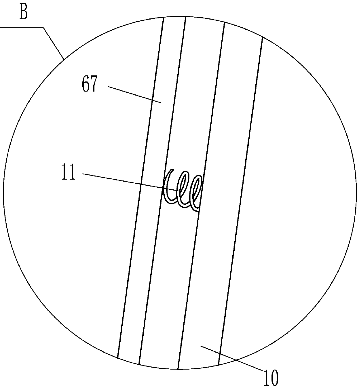
[0033] It also includes a contact plate 10 and a fourth spring 11 , the front side of the pressing plate 67 is slidably embedded with the contact plate 10 , and the fourth spring 11 is evenly spaced between the back side of the contact plate 10 and the inside of the pressing plate 67 .

[0034] When it is necessary...


PUM


Abstract

The invention relates to a material dipping machine, and especially relates to a material dipping machine for matchstick processing. The technical problem to be solved is how to design the material sticking machine for matchstick processing, which can replace manual work to scrape medicine materials flat, prevent hand ache from influencing the working efficiency and enable matchstick stems to be stuck with materials uniformly. The material dipping machine for matchstick processing comprises: a base, wherein supporting rods are symmetrically and fixedly connected to the edge of one side of thebase; and a loading frame mounted among the end parts, away from the base, of the four supporting rods. Medicine materials are poured into the loading frame, a pedal is treaded, a scraping plate can move backwards to scrape the medicine materials flat, and then one end of a matchstick stem is inserted into the medicine materials and is stained with the medicine materials to complete matchstick manufacturing, so people do not need to manually scrape the medicine materials flat with tools, and the situation that the working efficiency is affected by hand ache is avoided.

Description

technical field [0001] The invention relates to a dipping machine, in particular to a dipping machine for match processing. Background technique [0002] Match is based on the principle of heat generation by friction of objects, using the chemical activity of strong oxidizing agents and reducing agents to manufacture a kind of fire-making tool that can be ignited by friction. In the second half of the eighteenth century, yellow phosphorus was mainly used as a propellant. Because yellow phosphorus is poisonous, it was gradually replaced by phosphorus sulfide matches. Although the latter is non-toxic, it has the possibility of spontaneous combustion at any time, which is very unsafe. In 1855, the world's first match factory established in Sweden successfully developed safety matches, which were gradually adopted by countries all over the world. During the matchmaking process, it is necessary to dip the end of the matchstick with an appropriate amount of medicine to complete...

Claims


Application Information

Patent Timeline
Patent Type & Authority Applications(China)
IPC IPC(8): C06F1/06
CPCC06F1/06
Inventor 何红梅
Owner 临沂高新人才教育发展集团有限公司
Features
  • Generate Ideas
  • Intellectual Property
  • Life Sciences
  • Materials
  • Tech Scout
  • Unparalleled Data Quality
  • Higher Quality Content
  • 60% Fewer Hallucinations
Learn More