

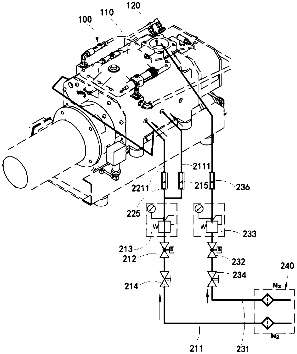
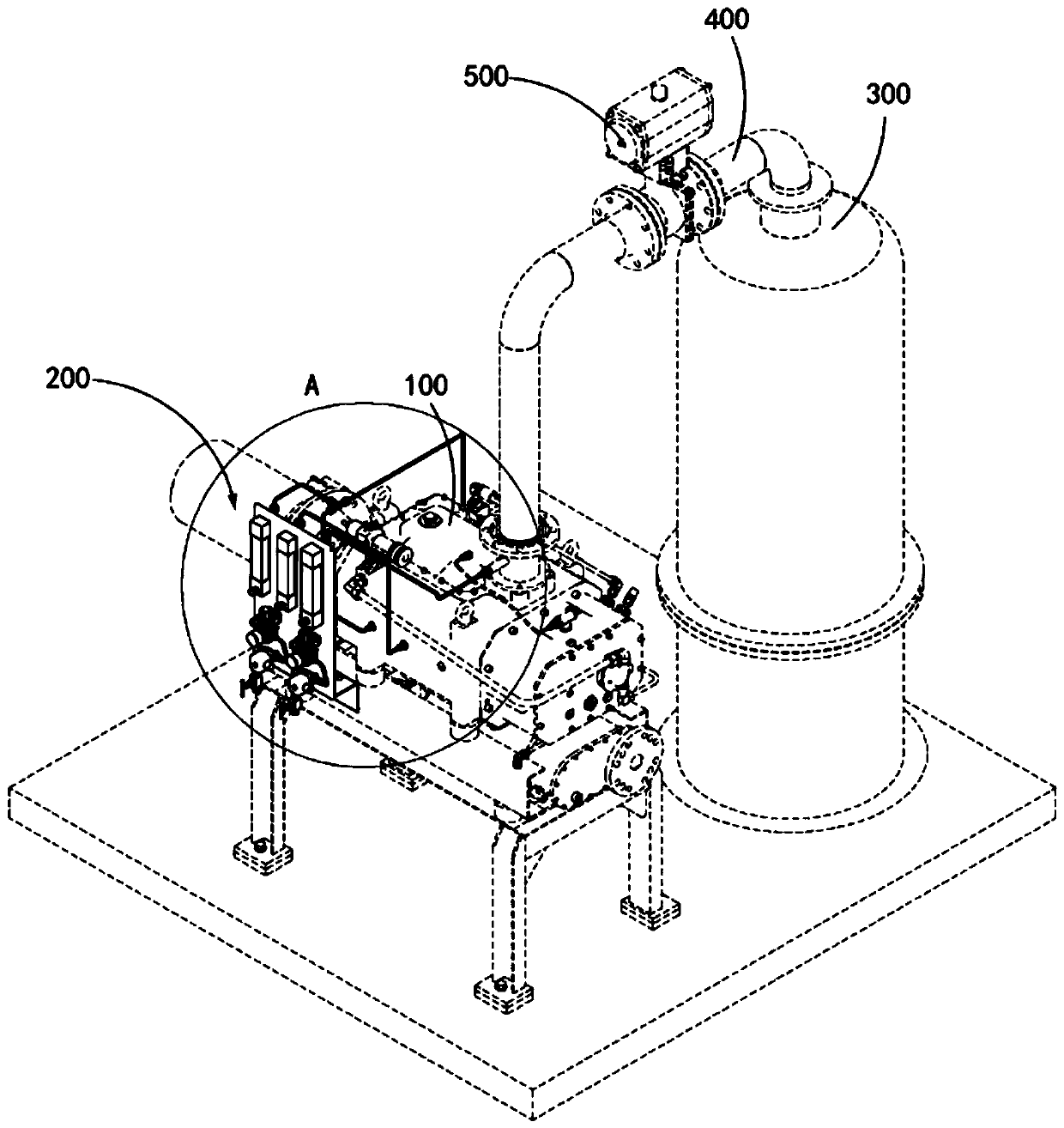
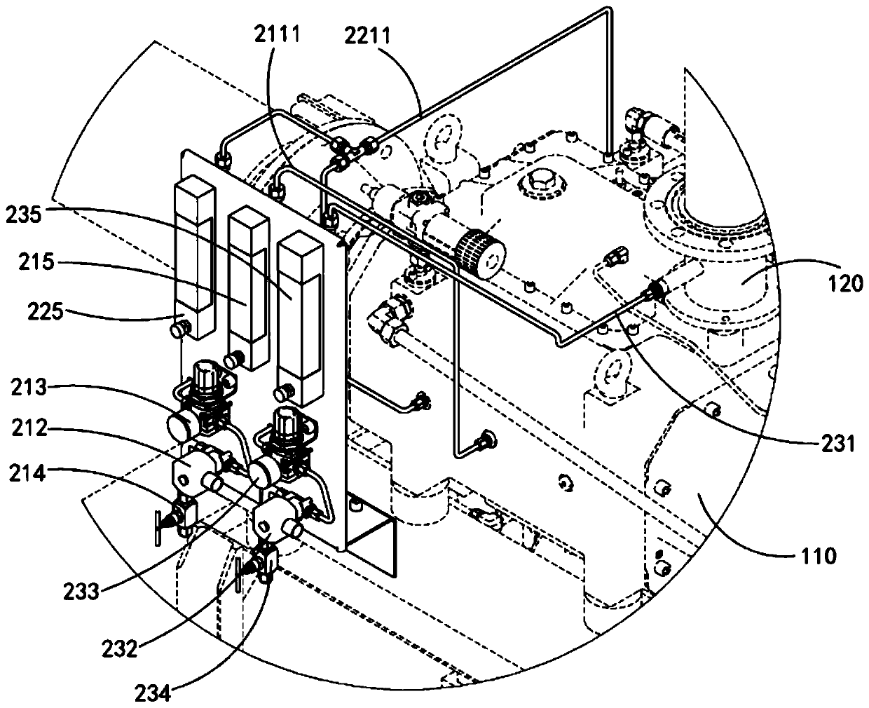
Dry vacuum pump and crude oil vacuum flash evaporation treatment device
A technology of dry vacuum pump and pump body, which is applied in the direction of vacuum distillation, distillation control/regulation of hydrocarbon oil, etc. It can solve the problems of vacuum pump stuck, gear wear, accumulation of pump chamber cannot be discharged in time, etc., to ensure vacuum degree and cleanliness temperature, reduce condensation, and improve the effect of trouble-free operation time
- Summary
- Abstract
- Description
- Claims
- Application Information
AI Technical Summary
Problems solved by technology
Method used
Image

Examples
Embodiment Construction
[0045] Typical embodiments embodying the features and advantages of the present invention will be described in detail in the following description. It should be understood that the present invention can have various changes in different embodiments without departing from the scope of the present invention, and that the description and drawings therein are illustrative in nature and not intended to limit the present invention. invention.
[0046] In the following description of various exemplary embodiments of the invention, reference is made to the accompanying drawings, which form a part hereof, and in which are shown by way of example different exemplary structures, systems, and embodiments in which aspects of the invention may be implemented and steps. It is to be understood that other specific arrangements of components, structures, exemplary devices, systems and steps may be utilized and structural and functional modifications may be made without departing from the scope...
PUM
 Abstract
Description
Claims
Application Information