A drying device based on glass fiber cloth processing application

A glass fiber cloth and drying device technology, applied in textile processing machine accessories, textile material processing, textile material processing equipment configuration, etc., can solve the problem that the carbon fiber cloth cannot be heated evenly, the drying effect is not good, and the waste heat cannot be fully utilized and other problems to achieve the effect of avoiding vibration and prolonging the service life

Active Publication Date: 2022-06-07
台嘉成都玻纤有限公司
View PDF5 Cites 1 Cited by
  • Summary
  • Abstract
  • Description
  • Claims
  • Application Information

AI Technical Summary

Problems solved by technology

[0003] At present, during the processing of fiber cloth, it is necessary to dry the cleaned fiber cloth, but the drying effect of the existing fiber cloth drying device is not good, it cannot evenly heat the carbon fiber cloth, and it cannot be fully utilized. waste heat

Method used


Image

  • A drying device based on glass fiber cloth processing application
  • A drying device based on glass fiber cloth processing application
  • A drying device based on glass fiber cloth processing application

Examples


Embodiment 1

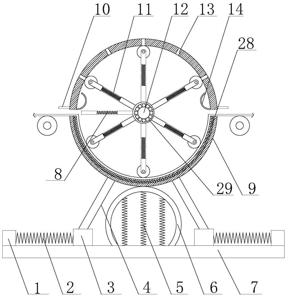
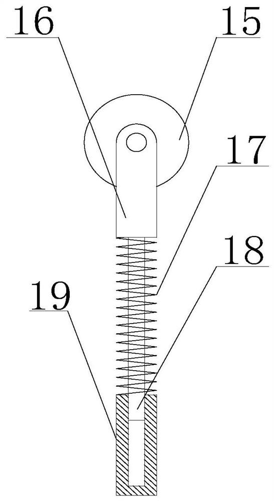
[0037] like Figure 1 to Figure 5 As shown, a drying device based on glass fiber cloth processing application of the present invention includes a base 7, a drying cylinder 9 is arranged above the base 7, and a drying cylinder 9 is provided between the drying cylinder 9 and the base 7. The two ends of the drying cylinder 9 are closed structures, and both sides of the circumferential outer wall of the drying cylinder 9 are provided with cloth inlets, and the two cloth inlets are located in the horizontal direction. There is also a heating wire 28 in the inner wall of the drying cylinder 9, and a fixing rod 12 is arranged in the drying cylinder 9. The fixing rods 12 are distributed along the axial direction of the drying cylinder 9, and the fixing rod 12 is provided with the fixing rod 12. The matching bearing 29, a plurality of telescopic rods 11 are arranged on the outer circumferential wall of the bearing 29, the telescopic rods 11 are distributed in a circular array around th...

Embodiment 2

[0039] On the basis of Embodiment 1, the damping assembly includes an arc-shaped curved plate 6 and a plurality of second damping members 5, the curved plate 6 has elasticity, and the two ends of the curved plate 6 are respectively connected to the top of the base 7, One end of the second shock absorbing member 5 is connected to the top of the base 7 , and the other end is connected to the curved surface of the curved plate 6 .

Embodiment 3

[0041] On the basis of Embodiment 2, the shock absorber assembly further includes two bumps 1 , two sliders 3 , two first shock absorbers 2 , two diagonal struts 4 , and two of the sliders 3 Located on both sides of the curved plate 6 and close to the end of the base 7 , the sliders 3 are respectively located between the curved plate 6 and the bump 1 , and one end of the first shock absorbing member 2 is connected to the bump 1 , the other end is connected with the sliding block 3 , one end of the diagonal strut 4 is hinged with the drying cylinder 9 , and the other end is hinged with the sliding block 3 .


PUM


Abstract

The invention discloses a drying device based on the processing and application of glass fiber cloth. There are cloth inlets on both sides of the outer wall, and the two cloth inlets are located in the horizontal direction. There is also a heating wire inside the inner wall of the drying cylinder. There is a fixed rod inside the drying cylinder. Distributed in the direction, the fixed rod is equipped with a bearing that matches the fixed rod, and the outer wall of the bearing is provided with a number of telescopic rods. The telescopic rods are distributed in a circular array around the axis of the fixed rod, and the telescopic rods are facing the inner wall of the drying cylinder. There are rollers at the end of the direction; both sides of the inner wall of the drying cylinder are equipped with liquid collecting plates; the outer wall of the bearing is also equipped with a holding assembly for holding the fiber cloth. The invention can evenly heat the fiber cloth, and can effectively benefit the residual heat to reheat the fiber cloth, so as to improve the drying efficiency of the fiber cloth.

Description

technical field [0001] The invention relates to the technical field of glass fiber cloth processing, in particular to a drying device based on glass fiber cloth processing and application. Background technique [0002] Fiberglass gingham is an untwisted roving plain weave, which is an important base material for hand-laid glass fiber reinforced plastics. The strength of the gingham fabric is mainly in the warp and weft direction of the fabric. For occasions requiring high warp or weft strength, it can also be woven into a unidirectional fabric, which can arrange more untwisted rovings in the warp or weft direction. Warp fabric, single weft fabric. Untwisted rovings are bundled from parallel strands or parallel monofilaments. According to the glass composition, roving can be divided into: alkali-free glass roving and medium-alkali glass roving. [0003] At present, in the process of processing the fiber cloth, it is necessary to dry the cleaned fiber cloth, but the drying ...

Claims


Application Information

Patent Timeline
Patent Type & Authority Patents(China)
IPC IPC(8): D06B15/00D06B23/02D06B23/20
CPCD06B15/00D06B23/028D06B23/026D06B23/20Y02P70/10
Inventor 林嘉佑
Owner 台嘉成都玻纤有限公司
Why Eureka
Try Eureka