Riverway sludge removing device

A technology for cleaning device and river channel silt, which is applied to mechanically driven excavators/dredgers, earth movers/shovels, construction, etc. It can solve the problems of inappropriate setting of filter screens, blockage in pipes, large suction volume, etc. problem, to achieve the effect of keeping the silt suction pipe unobstructed

Inactive Publication Date: 2020-08-07
孟好
View PDF0 Cites 0 Cited by
  • Summary
  • Abstract
  • Description
  • Claims
  • Application Information

AI Technical Summary

Problems solved by technology

[0005] In order to solve the above technical problems, the present invention provides a river silt cleaning device to solve the problem that when the existing river silt is sucked, because the suction head goes deep into the river water and is located on the river bed, although there is a lot of silt in the river, it is still There are dead branches and gravels, and the uncertainty of their size is too high. When the suction head sucks the sludge, it is easy to absorb dead branches and gravels at the same time. Due to the large suction volume, it is not easy to Suitable for setting the filter screen, causing the problem of easy clogging inside the pipe

Method used


Image

  • Riverway sludge removing device
  • Riverway sludge removing device
  • Riverway sludge removing device

Examples


Embodiment 1

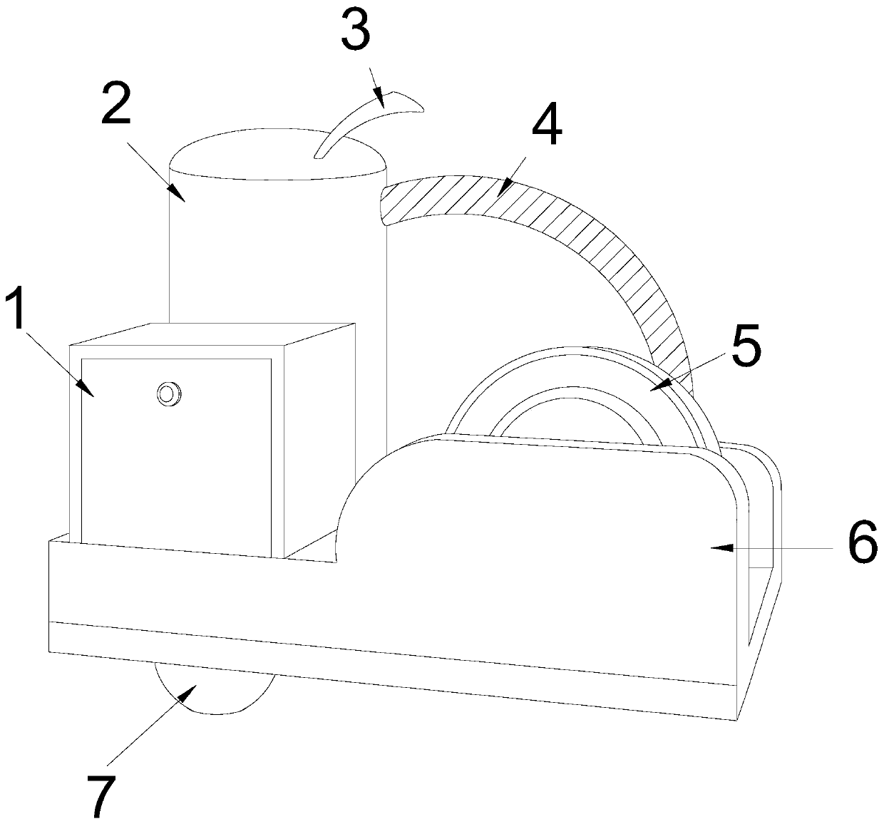
[0030] As attached figure 1 Attached Image 6 Shown:

[0031] The present invention provides a river silt cleaning device, which has a structure including a power box 1, a pressurizer 2, a pressurized spray pipe 3, a suction pipe 4, a pump 5, a support base 6, and a suction rotary device 7. The power box 1 is welded and fixed on the support base 6, the bottom of the press 2 is welded and fixed on the support base 6, and the suction pipe 4 is connected to the pump 5 and the press 2. The pump 5 and the suction rotary device 7 are fixedly connected together, and the pump 5 is welded and fixed on the support base 6.

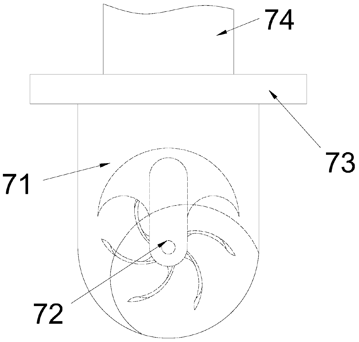
[0032] The suction and rotation device 7 includes a suction isolation sleeve 71, a rotation mechanism 72, a vertical ring 73, and a sludge suction pipe 74. The suction isolation sleeve 71 is welded to the vertical ring 73, and the inside of the suction isolation sleeve 71 A rotary mechanism 72 is provided, and the sludge suction pipe 74 is fixedly connected with the ver...

Embodiment 2

[0040] As attached Figure 7 Attached Figure 8 Shown:

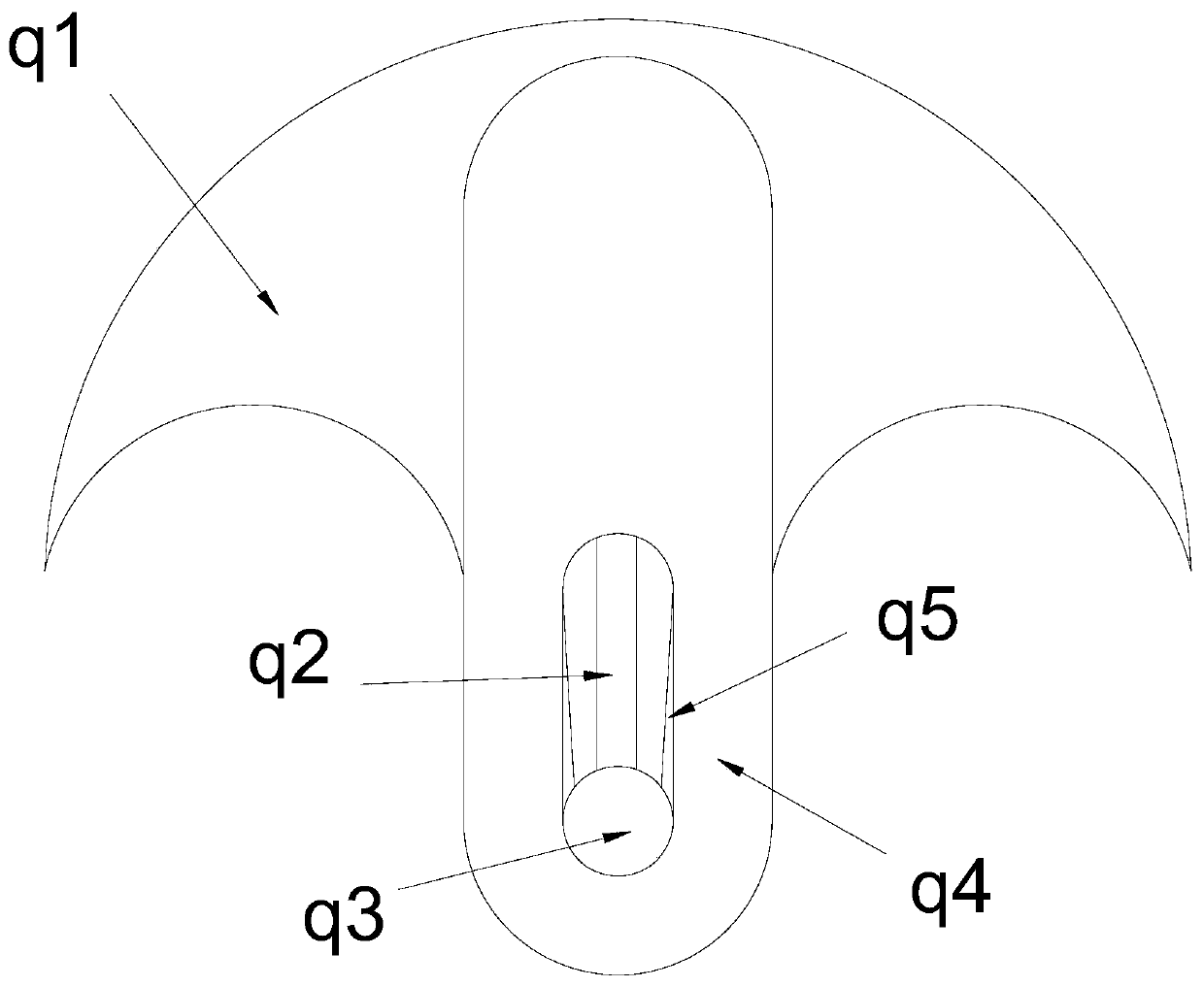
[0041] The present invention provides a device for cleaning river silt. The shifting strip 721 includes an outer shifting piece a1, a floating plate a2, a scale a3, and a connecting strip a4. The floating plate a2 is installed in the middle of the outer shifting piece a1 by embedding. The scale a3 is fixed on the outer surface of the outer paddle a1, the connecting strip a4 is fixedly connected to the outer paddle a1, and the outer paddle a1 has scales a3 that can be rotated on the outer stones and branches. When, it has a strong protective effect.

[0042] Wherein, the bottom of the pressing rod q2 is provided with a semicircular arc sleeve, and the inner surface of the sleeve strip has a smooth coating.

[0043] Wherein, the left and right sides of the floating plate a2 extend out of the inner covering surface of the outer paddle a1, and the left and right sides of the floating plate a2 are in a bare state, which can be ful...


PUM


Abstract

The invention provides a riverway sludge removing device which structurally comprises an electric power box, a pressurizing machine, a pressurizing injection pipe, a suction pipe, a pump machine, a supporting bottom frame and a sucking rotary shifting device. The electric power box is fixedly welded on the supporting bottom frame, the bottom of the pressurizing machine is fixedly welded on the supporting bottom frame, and the suction pipe is connected with the pump machine and the pressurizing machine. During suction, for continuous upturning of a reverse suction mechanism, a rotary wheel is lowered, the rotary wheel can be enabled to rotate anticlockwise under the control of buoyancy in water in the suction process, sludge on a river bed can be sucked, meanwhile, larger sundries which areattached and sucked can be pushed open in an impact mode, the stable suction state can be kept under the running working state of a rotary shifting mechanism, and the sludge suction pipe can be keptsmooth.

Description

Technical field [0001] The invention belongs to the field of environmental protection treatment, and more specifically, relates to a cleaning device for river silt. Background technique [0002] For river silt cleaning, a silt suction machine is generally placed on a boat, and the silt in the river is sucked by the suction machine. Since the width of the river is generally not too long, the high pressure spray force formed by the pressure-maintaining suction force can spray the silt To the bank, the plants on the river bank can be fertilized by the manure accumulated in the silt in the river. [0003] Based on the above description, the inventor found that the existing river silt cleaning device mainly has the following shortcomings, such as: [0004] When the river silt is pumped, because the suction head goes deep into the river water and is located on the river bed, although there is a lot of silt in the river, there are still dead branches and gravel, and the uncertainty of its ...

Claims


Application Information

Patent Timeline
Patent Type & Authority Applications(China)
IPC IPC(8): E02F3/88E02F3/90E02F3/92E02F5/28
CPCE02F3/88E02F3/90E02F3/92E02F3/9256E02F3/9293E02F5/28
Inventor 孟好
Owner 孟好
Why Eureka
Try Eureka