Floor drain sewer dredging equipment and method capable of instantly changing air pressure
A technology that instantly changes air pressure and is applied to waterway systems, water supply devices, drainage structures, etc. It can solve the problems of inconvenient use of suction dredging equipment, easy blockage of sewer pipes, and high cost of floor drains, so as to achieve convenient and fast use and increase circulation. Speed, using labor-saving effect
- Summary
- Abstract
- Description
- Claims
- Application Information
AI Technical Summary
Problems solved by technology
Method used
Image
Examples
Embodiment 1
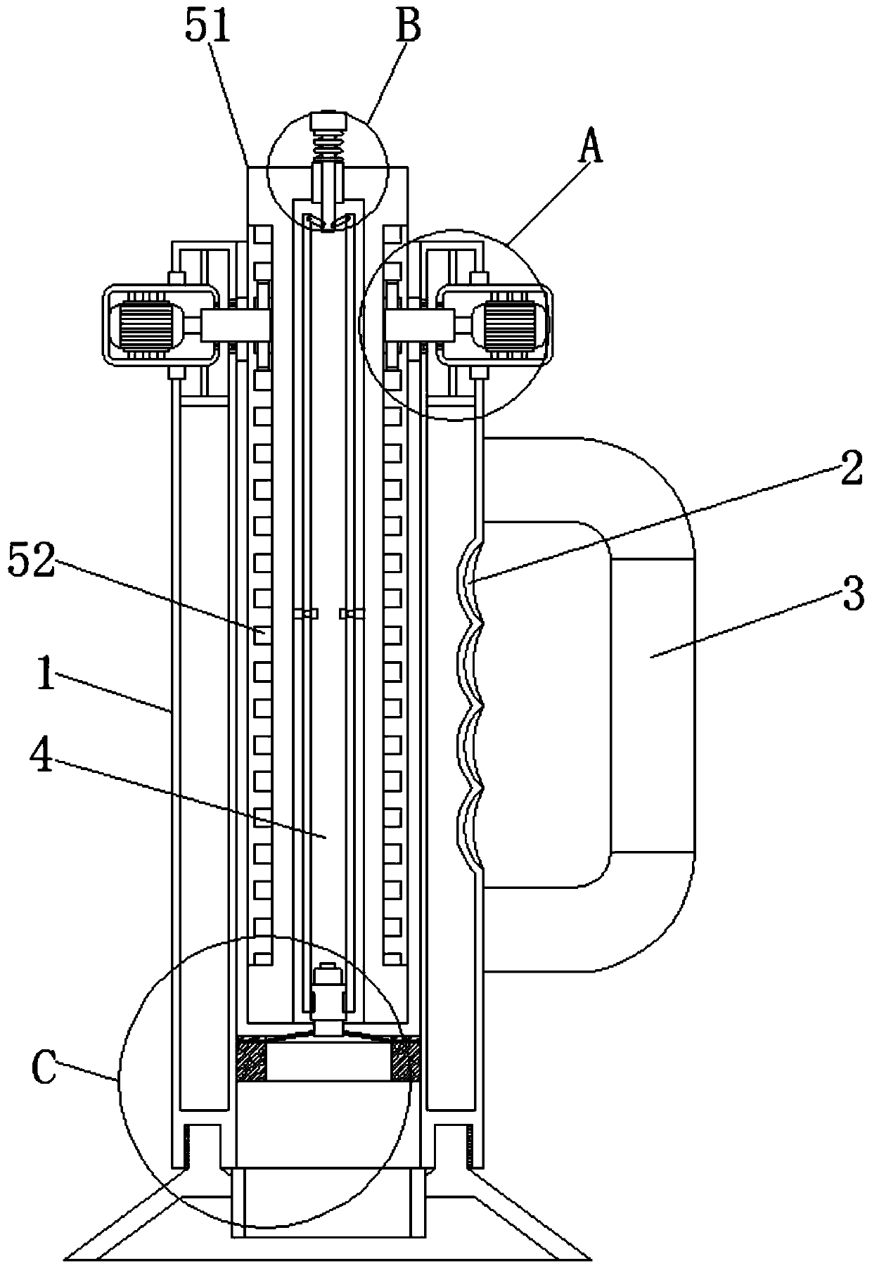
[0032] Such as Figure 1-5 As shown, a floor drain sewer dredging device and method that instantly changes the air pressure includes a support column 1, a finger mark groove 2 is provided in the middle of one side of the support column 1, and the finger mark groove 2 fits fingers, and the middle part of one side of the support column 1 is fixed. A handle 3 is connected, and the surface of the handle 3 is provided with anti-slip lines. The finger mark groove 2 cooperates with the handle 3 to facilitate holding. The middle part of the support column 1 is provided with a through hole 4 connecting its top and bottom. The air pressure changing mechanism 5 is provided with an annular thread groove 6 on four sides of the bottom of the support column 1 , and a sealing connection mechanism 7 is provided at the bottom of the support column 1 .
Embodiment 2
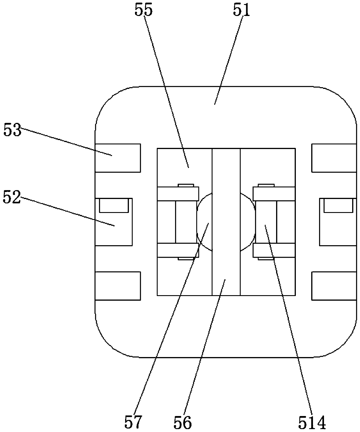
[0034]On the basis of Embodiment 1, the air pressure changing mechanism 5 includes a moving column 51, and the center of the moving column 51 is symmetrically provided with tooth grooves 52, and the front and back sides of the moving column 51 are symmetrically provided with chute 53, and the moving column 51 The tops on both sides are symmetrically provided with driving mechanisms 54, the middle of the bottom of the moving column 51 is provided with a moving groove 55, the bottom of the moving groove 55 inner cavity is provided with a support rod 56, and the center of the bottom of the support rod 56 is fixedly connected with a magnetic disk 57, and the magnetic disk 57 The bottom of the connecting cap 58 is adsorbed with a connecting cap 58, and the center of both sides of the connecting cap 58 is symmetrically provided with a card slot 59, and the center of the bottom of the connecting cap 58 is fixedly connected with a connecting block 521, and the bottom of the four sides o...
Embodiment 3
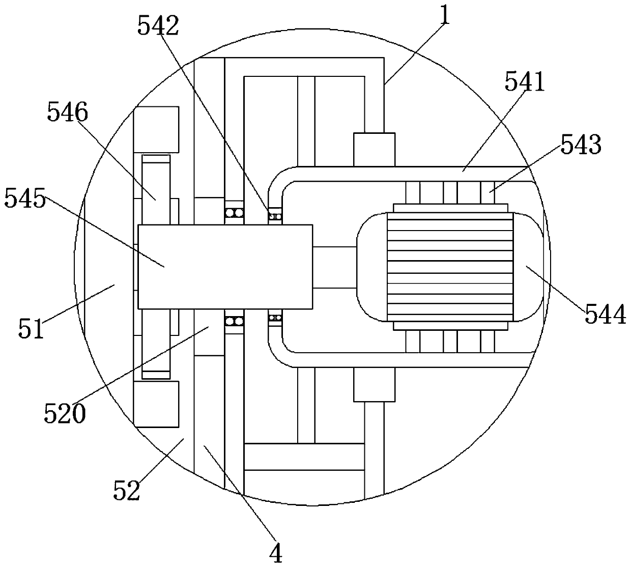
[0036] On the basis of Embodiments 1 and 2, the driving mechanism 54 includes a pressure-bearing box 541, and a second opening is opened in the middle of the opposite side of the pressure-bearing box 541 on both sides. The middle part of the top and bottom of the inner wall of the box 541 is symmetrically fixedly connected with a support frame 543, and the middle of the other side of the inner wall of the pressure box 541 is fixedly connected with a motor 544. An output shaft is extended, and the end of the output shaft of the motor 544 is fixedly connected with a rotating shaft 545 , and the end of the rotating shaft 545 away from the motor 544 is fixedly connected with a gear 546 .
PUM
 Abstract
Description
Claims
Application Information
 - R&D
- Intellectual Property
- Life Sciences
- Materials
- Tech Scout
- Unparalleled Data Quality
- Higher Quality Content
- 60% Fewer Hallucinations
Browse by: Latest US Patents, China's latest patents, Technical Efficacy Thesaurus, Application Domain, Technology Topic, Popular Technical Reports.
© 2025 PatSnap. All rights reserved.Legal|Privacy policy|Modern Slavery Act Transparency Statement|Sitemap|About US| Contact US: help@patsnap.com


