Floor tile laying device for building

A laying device and a technology for using floor tiles, which are applied in the direction of construction and building construction, can solve the problems of unstable manual operation of technical workers, low efficiency of laying tiles on the ground, and high technical content, achieving good application prospects and improving the bonding effect , the effect of good fit precision

Active Publication Date: 2020-08-07
新疆恒瑞建安工程建设有限公司
View PDF27 Cites 12 Cited by
  • Summary
  • Abstract
  • Description
  • Claims
  • Application Information

AI Technical Summary

Problems solved by technology

[0003] Because the dry laying method of floor tiles is more labor-intensive and has higher technical content, the cost of the dry laying method is much higher than that of the wet laying method; The efficiency of laying bricks is low and the quality varies; furthermore, a device for laying floor tiles for construction is proposed

Method used


Image

  • Floor tile laying device for building
  • Floor tile laying device for building
  • Floor tile laying device for building

Examples


Embodiment 1

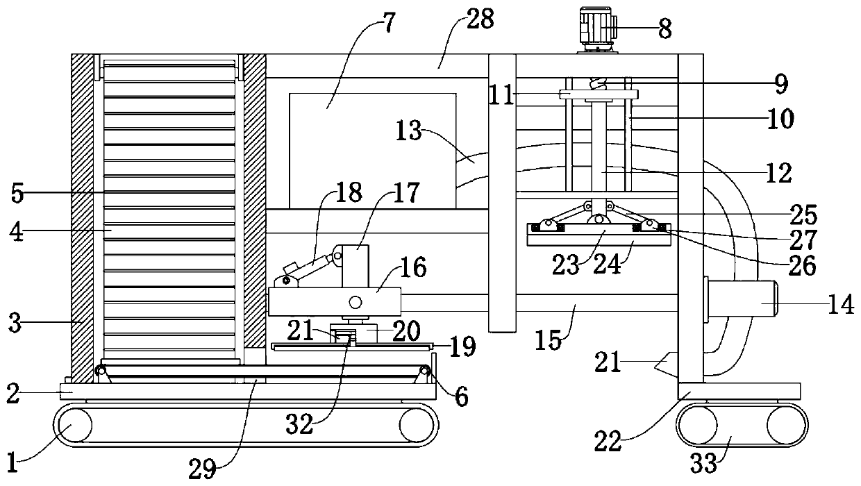
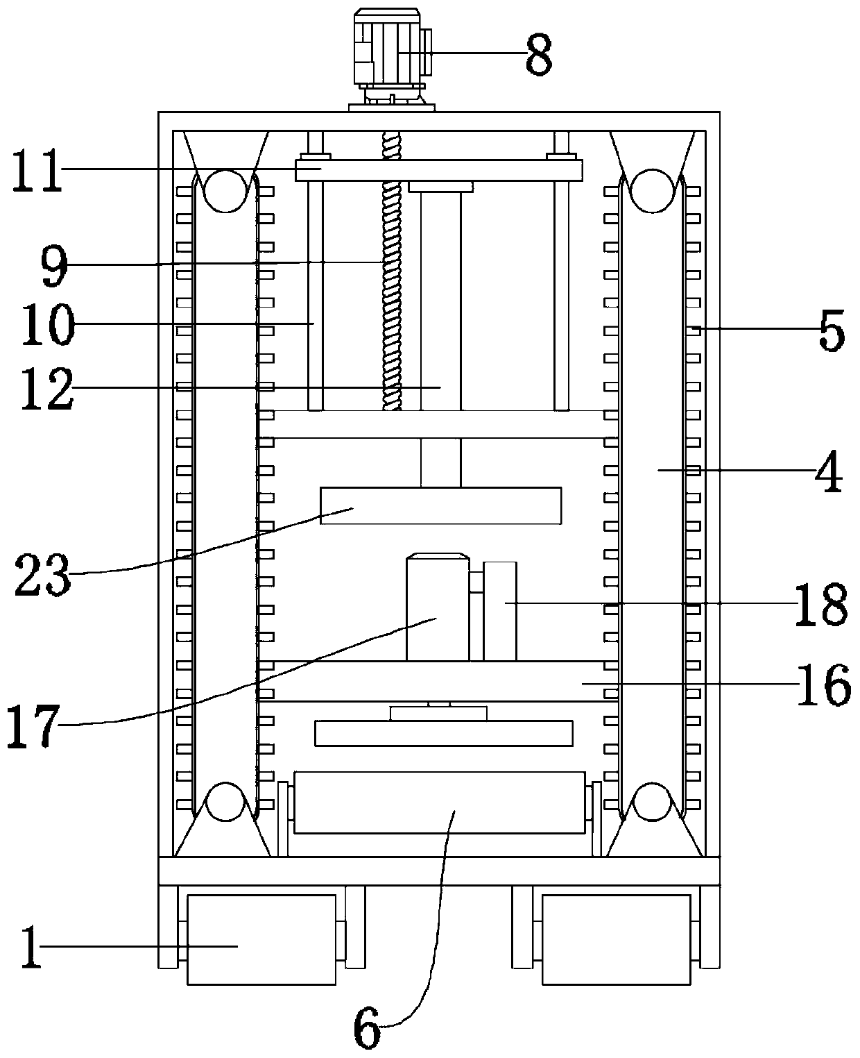
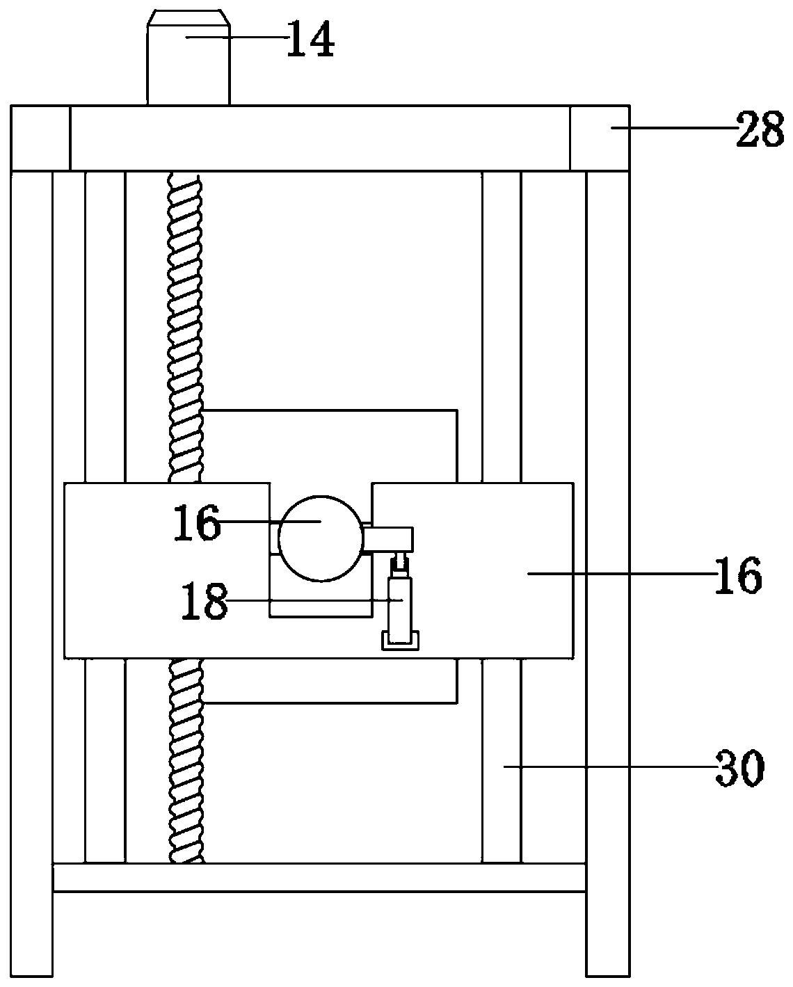
[0027] See Figure 1-3 , A construction floor tile laying device, including a bottom plate 2. The bottom of the bottom plate 2 is rotatably installed with a drive wheel 1 equipped with a power mechanism, and the bottom plate 2 is further driven to move by the drive wheel 1, and the bottom plate 2 is fixedly installed for storage of the floor tiles 31 The device, one side of the storage device is fixedly connected with a bracket 28, the device is built with a frame structure through the bracket 28, and the discharging device, the vibration device and the transfer device are fixedly installed on the frame structure; and the device is in use , The floor tiles 31 are output from the storage device, and the floor tiles 31 are transported through the transfer device. During the transportation of the floor tiles 31, the vibration device achieves vibration and hydraulic leveling against the ground, and the discharge device described later is flattened. Spray the mud on the bonding surf...

Embodiment 2

[0041] See Figure 4 The end of the conveying pipe 13 is inclined cloth, and the opening direction is inclined upward; when the clamping device clamps the floor tiles 31 and rotates a certain angle, the mud in the conveying pipe 13 is sprayed on the bonding surface of the floor tiles 31.

[0042] The working principle of this embodiment: the end of the conveying pipe 13 is inclined and the opening direction is inclined upward; when the clamping device clamps the floor tiles 31 and rotates a certain angle, the mud in the conveying pipe 13 is exactly sprayed onto the floor tiles 31 Surface.

[0043] It should be noted that the lifting motor and the transfer motor in this application are applications of the prior art. The transfer device and the vibration device are driven by the screw drive, which has the characteristics of small transmission torque, accurate transmission, and labor saving, and reduces the motor load; At the same time, the vibration plate 24 is an application of the ...


PUM


Abstract

The invention discloses a floor tile laying device for a building. The floor tile laying device for the building comprises a bottom plate, driving wheels with power mechanisms are rotationally installed at the bottom of the bottom plate, a storage device used for storing floor tiles is fixedly installed on the bottom plate, a support is fixedly connected to one side of the storage device, a framestructure is built through the support, and a discharging device, a vibrating device and a transferring device are fixedly mounted on the frame structure. The floor tile laying device is reasonable instructure, practical and suitable for large-area floor tile laying; and the transferring device and the vibrating device are driven to move through lead screw transmission, the characteristics of being small in transmission torque, accurate in transmission and capable of saving labor are achieved, and motor loads are reduced; and meanwhile, on one hand, belt wheels support the frame structure, onthe other hand, the floor tiles which are completely attached are pressed through the belt wheels, and the attaching effect is improved. The floor tile laying device has good stability and attachingprecision, and has a good application prospect.

Description

Technical field [0001] The invention relates to the field of construction, in particular to a floor tile laying device for construction. Background technique [0002] Floor tiles are a kind of floor decoration materials, also called floor tiles. Fired with clay. Various specifications. Strong, pressure and wear resistance, and moisture-proof. Some have been glazed for decoration. It is mostly used on the ground and floor of public buildings and civil buildings. When laying the floor tiles, in theory, the floor tiles should be dry-laid. After the base layer is watered and moistened, the floating sand and debris are removed. Spread the bonding layer, use a one-to-three dry cement mortar, follow the horizontal line to flatten, place the bricks on the mortar and use a rubber hammer to vibrate, remove the floor tiles and pour the cement grout, and then put the floor tiles firmly and flatten. . The dry paving method effectively avoids the occurrence of air bubbles and hollowing ...

Claims


Application Information

Patent Timeline
Patent Type & Authority Applications(China)
IPC IPC(8): E04F21/22
CPCE04F21/22
Inventor 巴秀英
Owner 新疆恒瑞建安工程建设有限公司
Why Eureka
Try Eureka