
A kind of reconfigurable compound eye system and working method

A compound eye and variable technology, applied in the field of bionic compound eye system, can solve the problems of imaging dead angle, long-term deployment, low imaging resolution, etc., and achieve the effect of adjustable geometric position relationship

Active Publication Date: 2021-02-02
WUHAN UNIV OF TECH
View PDF6 Cites 0 Cited by
  • Summary
  • Abstract
  • Description
  • Claims
  • Application Information

AI Technical Summary

Problems solved by technology

As a new type of visual system, the bionic compound eye system has the advantages of large field of view, light weight, and can be applied to complex application environments. It is widely used in radar systems, micro aircraft, micro compound eyes, and sports robots. There are defects such as small field of view, low imaging resolution, and imaging dead angle
[0003] Existing bionic compound eye systems generally use multi-faceted fiber optic panels to collect light information in different directions or curved surface compound eye systems to solve the above problems. The geometric position between the eyes is difficult to adjust quickly and dynamically, and it takes a long time to deploy in complex situations

Method used


Image

  • A kind of reconfigurable compound eye system and working method
  • A kind of reconfigurable compound eye system and working method
  • A kind of reconfigurable compound eye system and working method

Examples


Embodiment Construction

[0040] The following will clearly and completely describe the technical solutions in the embodiments of the present invention with reference to the drawings in the embodiments of the present invention.

[0041] In describing the present invention, it should be understood that the terms "center", "longitudinal", "transverse", "upper", "lower", "front", "rear", "left", "right", " The orientations or positional relationships indicated by "vertical", "horizontal", "top", "bottom", "inner" and "outer" are based on the orientations or positional relationships shown in the drawings, and are only for the convenience of describing the present invention and Simplified descriptions, rather than indicating or implying that the device or element referred to must have a particular orientation, be constructed and operate in a particular orientation, and thus should not be construed as limiting the invention. In addition, the terms "first", "second", etc. are used for descriptive purposes onl...


PUM


Abstract

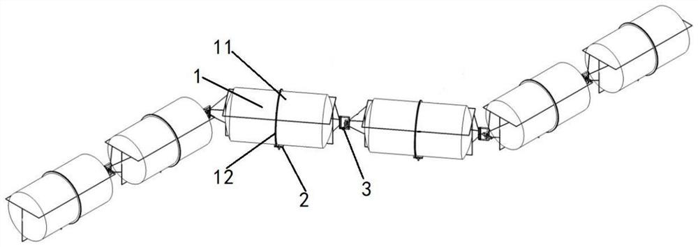
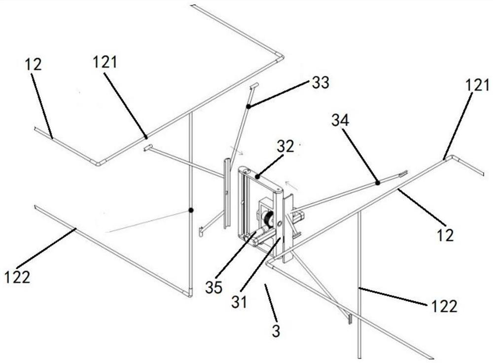
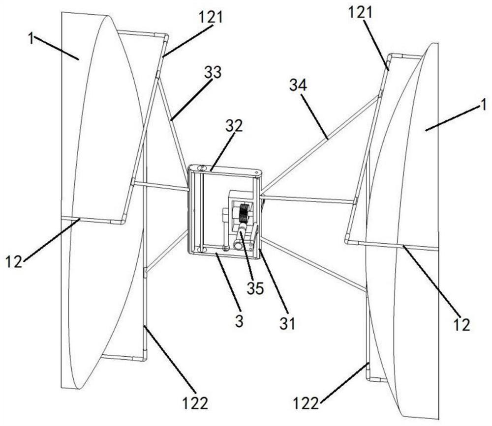
The invention discloses a variable-constitutable compound eye system and a working method, which include a plurality of sequentially connected body segments, the body segment includes an airbag and an airbag bracket, the airbag bracket is arranged outside the airbag, and the airbag is provided with a data acquisition device, the data acquisition device Including ring rack, gear, first drive source, equipment compartment and sub-eye, the ring rack ring is arranged outside the airbag, the first drive source is installed on the top of the equipment compartment and a gear meshed with the ring rack, and the sub-eye is installed on the equipment At the bottom of the cabin, the adjacent body segments are connected by a swing mechanism. The swing mechanism includes a swing base, a swing arm, a first connecting bracket and a second connecting bracket. The swing arm is hinged to the swing base, and the swing base is provided with a driving swing arm. The second driving source of the swing, the first connecting bracket connects the swing base and a body segment, the second connecting bracket connects the swing arm and another body segment, the geometric position relationship between each sub-eye is adjustable, and can adapt to different heights , the needs of image acquisition on different occasions.

Description

technical field [0001] The invention relates to the technical field of bionic compound eye systems, in particular to a variable-configurable compound eye system and a working method. Background technique [0002] Now unmanned aerial vehicles have been widely used in military investigation and detection, missile early warning, aerial photography, security monitoring, search and rescue in disaster areas and many other fields. As a new type of visual system, the bionic compound eye system has the advantages of large field of view, light weight, and can be applied to complex application environments. It is widely used in radar systems, micro aircraft, micro compound eyes, and sports robots. There are defects such as small field of view, low imaging resolution, and imaging dead angle. [0003] Existing bionic compound eye systems generally use multi-faceted fiber optic panels to collect light information in different directions or curved surface compound eye systems to solve the...

Claims


Application Information

Patent Timeline
Patent Type & Authority Patents(China)
IPC IPC(8): F16M11/04F16M11/12F16M11/18F16M11/42F16M13/02F16M7/00G06T3/40
CPCF16M7/00F16M11/04F16M11/121F16M11/18F16M11/425F16M13/02G06T3/4038
Inventor 王汉熙刘博蒋力群任子豪黄鑫
Owner WUHAN UNIV OF TECH
Learn More