Diaphragm air pressure tank and safety detection method thereof

A technology of safety detection and pressure tank, which is applied in the direction of measuring device, fluid tightness test, machine/structural component test, etc. It can solve the problem that the diaphragm pressure tank cannot provide the expected pressure stabilization and buffering function and affect the external pipe network system Water supply stability and other issues, to achieve the effect of good practicability and flexibility of use, good flexibility of use, and high detection efficiency

Inactive Publication Date: 2020-08-07
上海南汇压力容器厂有限公司
View PDF4 Cites 0 Cited by
  • Summary
  • Abstract
  • Description
  • Claims
  • Application Information

AI Technical Summary

Problems solved by technology

However, during the regular maintenance interval, it is easy to have an abnormal working time period when the diaphragm pressure

Method used


Image

  • Diaphragm air pressure tank and safety detection method thereof
  • Diaphragm air pressure tank and safety detection method thereof
  • Diaphragm air pressure tank and safety detection method thereof

Examples


Example Embodiment

[0039] Example one:

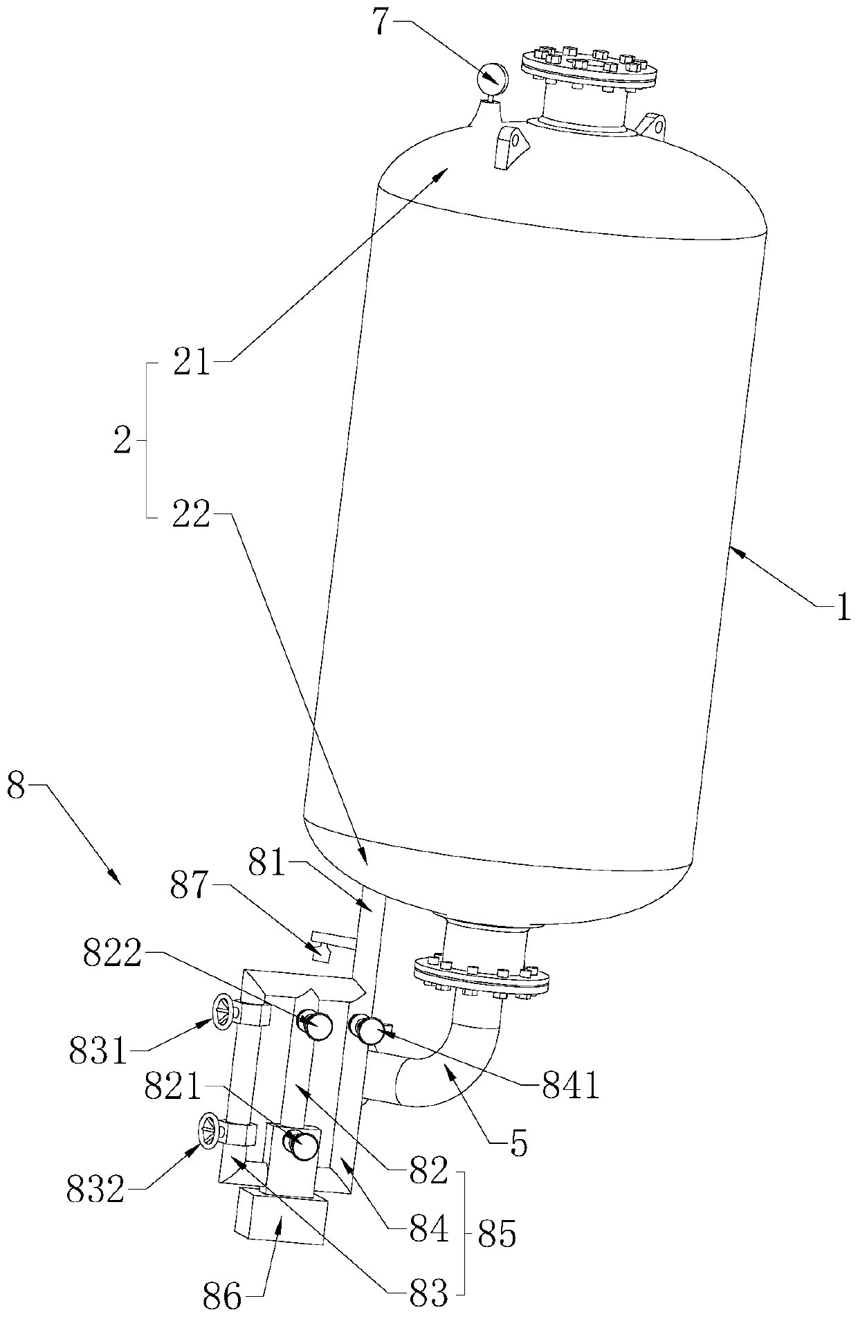
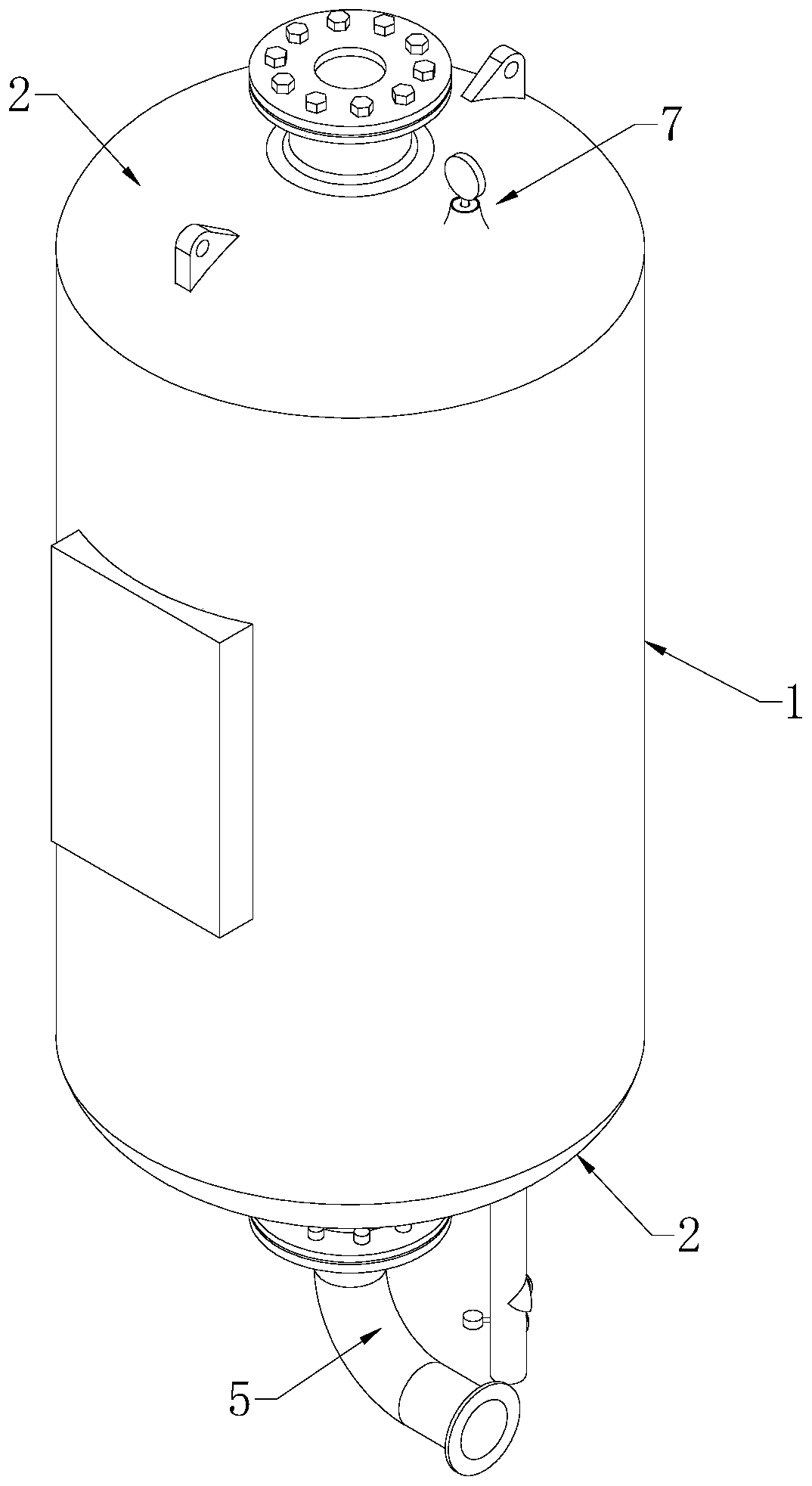
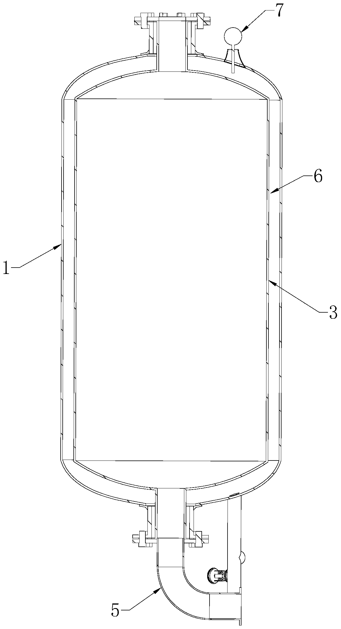
[0040] Combine figure 1 with image 3 As shown, a diaphragm gas pressure tank includes a can body 1 arranged vertically. The can body 1 has an upright cylindrical structure. The upper and lower ends of the can body 1 are welded with heads 2 which are in a bowl structure. A capsule 3 is installed inside the can body 1, and two ends of the capsule 3 are respectively penetrated with a corresponding head 2 and are fixedly connected with the head 2 through a flange. The head 2 includes an upper head 21, a head 2 and a lower head 22, a head 2, and the flange at the head 2 of the upper head 21 and the upper end of the capsule 3 are locked and sealed by bolts. Head 2; lower head 22 The flange at the head 2 and the lower end of the capsule 3 are connected by bolts to form an opening. The inlet and outlet pipes 5 are welded and installed at the openings. The inlet and outlet pipes 5 pass through the lower head 22 and communicate with the capsule 3, and the inlet and...

Example Embodiment

[0049] Embodiment two:

[0050] Such as Figure 5 As shown, a safety detection method for a diaphragm pressure tank includes the following steps:

[0051] S1. Perform flaw detection on the welded tank body 1. After the flaw detection is passed, the tank body 1 is assembled with the capsule 3. Then the main structure of the assembled diaphragm pressure tank is inflated, and the display state of the pressure gauge 7 is observed after the inflation is completed. It is necessary to observe whether it can display the pressure value normally, whether there is the phenomenon of the pointer swinging, if it can not display normally or the pointer swinging, the pressure gauge 7 needs to be replaced.

[0052] S2. Inject water into the main structure of the diaphragm pressure tank that has completed the display test of the pressure gauge 7 and detected normal, and observe the working status of the pressure gauge 7 during the water injection process and within the stable time period after the wat...


PUM


Abstract

The invention relates to a diaphragm air pressure tank and a safety detection method thereof, and relates to the technical field of pressure balance containers, the diaphragm air pressure tank comprises a tank body and a capsule, a cavity structure is formed between the tank body and the capsule, and a pressure gauge and an air supplementing device are arranged on the tank body. The air supplementing device comprises an air supplementing pipeline, the air supplementing pipeline is connected with an air storage pressure container, a first automatic valve is arranged on the air storage pressurecontainer, and a second automatic valve is arranged on the air supplementing pipeline; the air supplementing pipeline is connected with a bypass pipeline in parallel, the bypass pipeline is connectedwith the air storage pressure container, and a first manual valve and a second manual valve are arranged on the bypass pipeline. The air supplementing device further comprises a control module, the control module controls the first automatic valve and the second automatic valve in a linkage mode according to the detection numerical value of the pressure gauge, and therefore the purposes of automatic detection and air supplementing are achieved. An automatic air supply mode is combined with a manual air supply mode, so that the operation stability of the diaphragm air pressure tank and an external pipe network system connected with the diaphragm air pressure tank can be effectively improved.

Description

technical field [0001] The invention relates to the technical field of pressure balance containers, in particular to a diaphragm pressure tank and a safety detection method thereof. Background technique [0002] Diaphragm pressure tank is one of the essential components of a complete set of automatic water supply equipment. Its main function is to store energy and maintain pressure, and maintain the pressure of the pipe network system in the case of a small amount of water supply and pipe network leakage. When the water pressure of the pipe network system drops, the storage water stored in the diaphragm pressure tank can be replenished into the pipe network system under pressure to achieve the purpose of pressure supplement and buffer. [0003] combine figure 2 with image 3 As shown, in the prior art, the diaphragm pressure tank includes a tank body 1, a capsule 3 is installed in the tank body 1, and the two ends of the capsule 3 are respectively sealed and connected with...

Claims


Application Information

Patent Timeline
IPC IPC(8): G01M3/32E03B11/08E03B11/06
CPCE03B11/06E03B11/08G01M3/3236G01M3/3272
Inventor 徐锋
Owner 上海南汇压力容器厂有限公司
Why Eureka
Try Eureka