Millimeter wave sparse imaging method and system based on sparse array

A sparse array and sparse imaging technology, applied in the field of holographic imaging, can solve the problems of echo signal amplitude information without phase information, poor picture clarity, image blur, etc., to improve image resolution, reduce image blur, and reduce sending and receiving The effect of the number of machines

Active Publication Date: 2020-08-07
杭州芯影科技有限公司
View PDF7 Cites 6 Cited by
  • Summary
  • Abstract
  • Description
  • Claims
  • Application Information

AI Technical Summary

Problems solved by technology

[0006] However, passive imaging systems that can perform long-distance imaging can only form two-dimensional images. For example, the British Digitalbarriers TS4 / TS5 long-distance human body imaging system can image single-person walking targets. It uses 0.25THz passive imaging with long-distance time resolution It is larger than 5cm, but due to passive imaging, it only has amplitude information and no phase information for the acquisition of echo signals, so it cannot perform three-dimensional imaging, and can only form two-dimensional images similar to silhouettes; compared with the above three active imaging devices, in the same resolution In the case of low rate, the picture definition is poor, which is not conducive to the later image recognition
Especially indoor imaging requires auxiliary source irradiation, otherwise the temperature difference between the human body temperature and the temperature of the dangerous goods is not large, resulting in very blurred images
[0007] Therefore, for long-distance high-resolution 3D imaging, the resolution and details of the image formed by the current imaging system are far from enough to meet the application requirements.

Method used


Image

  • Millimeter wave sparse imaging method and system based on sparse array
  • Millimeter wave sparse imaging method and system based on sparse array
  • Millimeter wave sparse imaging method and system based on sparse array

Examples


Embodiment Construction

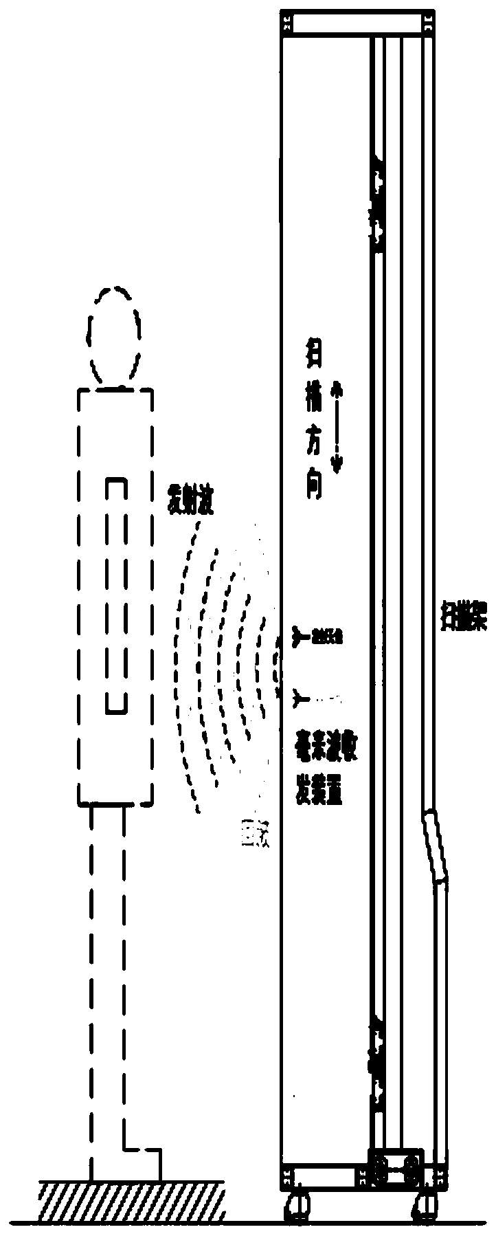
[0060] In order to better show the technical solution of the present invention, the present invention will be further described below in conjunction with the accompanying drawings.

[0061] The main structure of the millimeter wave security inspection imaging system, which is an active millimeter wave imaging security inspection instrument for cooperative human security inspection, is as follows image 3 As shown, the system uses a combination of electronic array scanning and mechanical scanning. The core is a 2×80 array element millimeter wave transmitting and receiving imaging front-end linear array. The horizontal direction depends on the imaging front-end linear array to switch through the switch for scanning, and the vertical direction passes through the imaging front-end line. The vertical mechanical motion scanning of the array is combined with the horizontal scanning of each line to perform multi-frequency point scanning to obtain the space-frequency three-dimensional elect...


PUM


Abstract

The invention provides a millimeter wave sparse imaging method and system based on a sparse array. The method comprises the steps of enabling original electromagnetic field data collected by the sparse array to be changed into first electromagnetic field data of a dense array according to a first equivalent principle, and enabling the first equivalent principle to comprise an equivalent change ofkeeping a sparse frequency point unchanged, changing the original electromagnetic field data into second electromagnetic field data on densely distributed frequency points according to a second equivalence principle, wherein the second equivalence principle comprises changes based on the densely distributed array under different frequency points, and imaging by adopting a millimeter wave holographic imaging algorithm according to the first electromagnetic field data and the second electromagnetic field data. The imaging definition of the long-distance millimeter wave imaging system can be improved.

Description

Technical field [0001] The invention relates to the technical field of holographic imaging, in particular to a sparse array-based millimeter wave sparse imaging method and a millimeter wave sparse imaging system based on the sparse array. Background technique [0002] In recent years, the international and domestic counter-terrorism situation has become increasingly severe, and security issues have become a common concern of the society of all countries, especially in important occasions where the pressure of personnel security inspections is huge, such as stations, airports, ports, customs clearance checkpoints, and large venues and gatherings. The security check pressure of personnel requiring fast passage. [0003] In the past, conventional security checks were directed to individual cooperating targets, mainly checking small items carried with them, such as lighters, knives, liquids, etc., and the more typical ones were security checks at the entrances of airports and train st...

Claims


Application Information

Patent Timeline
Patent Type & Authority Applications(China)
IPC IPC(8): G01V3/08
CPCG01V3/08
Inventor 吴亮杨明辉
Owner 杭州芯影科技有限公司
Why Eureka
Try Eureka