Aviation direct-current distribution relay

A technology of DC power distribution and relays, applied in the direction of electromagnetic relays, relays, detailed information of electromagnetic relays, etc., can solve problems such as instability

Pending Publication Date: 2020-08-07
CIVIL AVIATION FLIGHT UNIV OF CHINA
View PDF0 Cites 1 Cited by
  • Summary
  • Abstract
  • Description
  • Claims
  • Application Information

AI Technical Summary

Problems solved by technology

[0003] In the prior art, there is no corresponding equipment structure to effectively solve the problem of relay contact separation when the magnetic flux becomes small, and when the problem occurs, the voltage is usually artificially increased to keep the current large enough, and the magnetic flux can guarantee effective resistance The recovery force of the spring, and when the aircraft is flying in the air, no mistakes are allowed to ensure the safety of the entire aircraft. At present, it is not stable to control the closing of the relay simply by increasing the voltage. How can the relay be stably In the closed state, it is an urgent problem to be solved in the field of aviation power distribution equipment to avoid flight failures caused by the disconnection of the relay during the flight.

Method used


Image

  • Aviation direct-current distribution relay
  • Aviation direct-current distribution relay
  • Aviation direct-current distribution relay

Examples


Embodiment 1

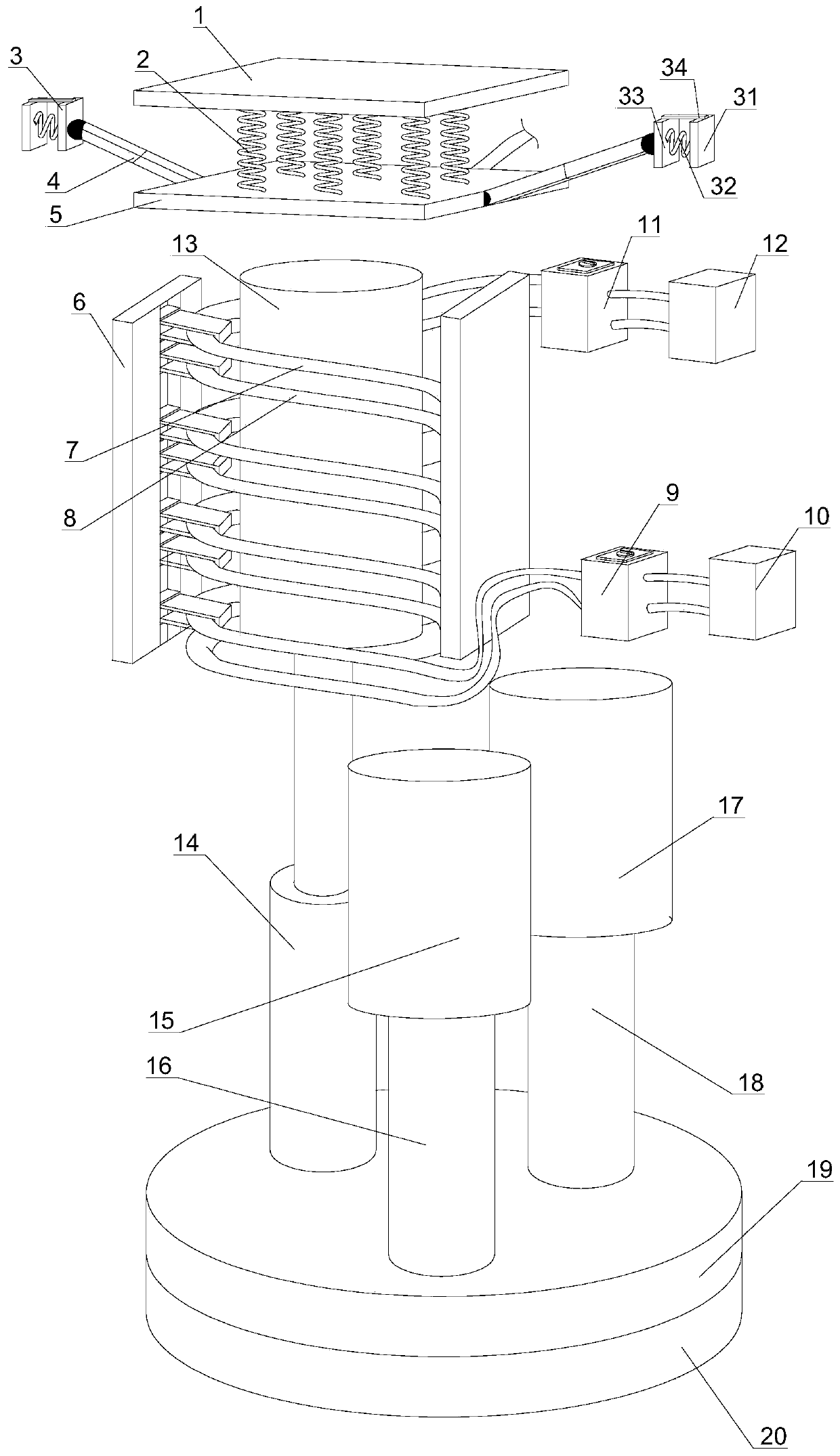
[0033] Such as Figure 1~3As shown, the aeronautical DC power distribution relay described in this implementation includes a top case 1, an attraction plate 5 is provided under the top case 1, and an elastic recovery member is provided between the attraction plate 5 and the top case 1, and the elastic recovery One end of the part is fixedly connected with the suction plate 5, and the other end of the elastic recovery part is fixedly connected with the top shell 1. The side of the suction plate 5 is provided with an extended fixed rod 4, and one end of the extended fixed rod 4 is hinged with the suction plate 5, extending The other end of the fixed rod 4 is provided with a telescopic buffer assembly 3, and the extended fixed rod 4 is hinged with the telescopic buffer assembly 3. A wire holder 6 is provided below the suction plate 5, and a group of first wire holders are coiled and fixed on the wire holder 6. One electric wire 7 and several groups of secondary electric wires, th...

Embodiment 2

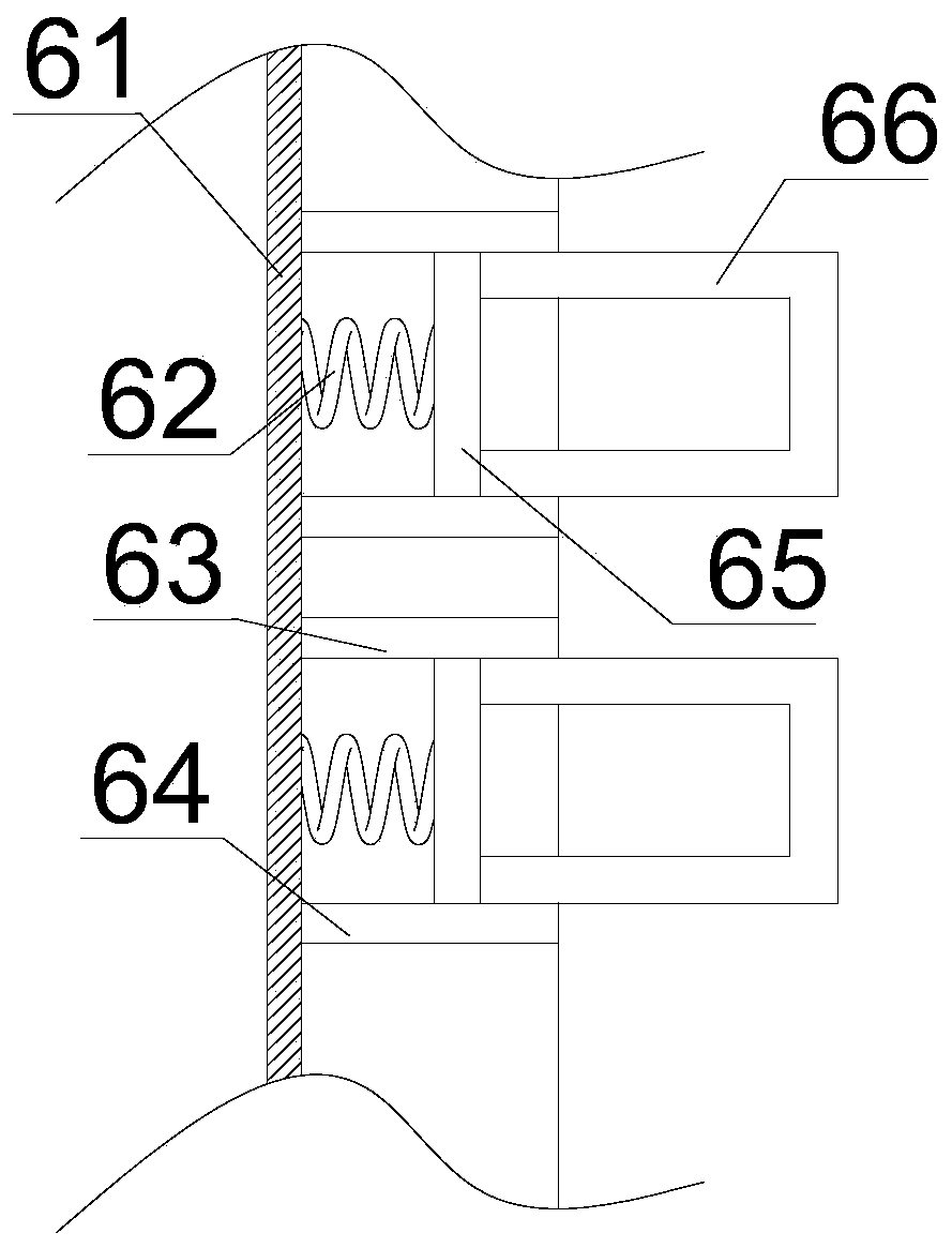
[0040] Such as Figure 1~4 As shown, on the basis of Embodiment 1, the secondary energizing wires are a set of second energizing wires 8, the lower tightening assembly 9 includes a tightening shell 97, and the upper surface of the tightening shell 97 is provided with Press the lock button 91, the press lock button 91 penetrates the upper surface of the tightening shell 97 and extends to the inside of the tightening shell 97, the lower surface of the press lock button 91 is provided with a lower pressing rod 94, and the lower pressing rod 94 is connected with the pressing lock The button 91 is fixed, and a reset plate 93 and two lower press plates 96 are sequentially arranged on the lower pressure rod 94 from top to bottom. The reset plate 93 extends away from the center of the push knob, and the lower press plate 96 extends toward the center of the push knob. , and the two lower pressure plates 96 are parallel to each other, and a reset extension spring 92 is also provided bet...

Embodiment 3

[0042] Such as Figure 1-5 As shown, on the basis of any one of embodiments 1 to 2, the push lock button 91 includes a knob housing 911, the upper surface of the knob housing 911 is provided with a rotating disk 919, and the upper surface of the rotating disk 919 is provided with a handle 920 , the handle 920 is fixed to the rotating disk 919, the lower surface of the rotating disk 919 is provided with a rotating shaft 921, the rotating shaft 921 runs through the rotating casing and extends to the inside of the rotating casing, one end of the rotating shaft 921 is fixed to the lower surface of the rotating disk 919, and rotates The other end of the shaft 921 is provided with a first horizontal gear 915, the side of the first horizontal gear is provided with a second horizontal gear 918, the first horizontal gear 915 and the second horizontal gear 918 mesh, the first horizontal gear 915 The bottom is provided with a first vertical gear 914, the first horizontal gear 915 meshes ...


PUM


Abstract

The invention discloses an aviation direct-current distribution relay. The relay comprises a top shell, and a suction plate is arranged below the top shell; an elastic recovery piece is arranged between the attraction plate and the top shell; an extension fixing rod is arranged on the side surface of the attraction plate; and the extension fixing rod is hinged to the telescopic buffer assembly. Anelectric wire fixing frame is arranged below the attraction plate; a first electrifying wire and a secondary electrifying wire are coiled and fixed on the electric wire fixing frame; the first electrifying wire and the secondary electrifying wire are coiled on the wire fixing frame to form a spiral coil; upper tightening assemblies are arranged at the upper ends of the first electrifying wire andthe secondary electrifying wire, lower tightening assemblies capable of tensioning the electrifying wires are arranged at the lower ends of the first electrifying wire and the secondary electrifyingwire, and the first electrifying wire and the secondary electrifying wire penetrate through the lower tightening assemblies and are connected to a lower electric cabinet. By adding the secondary electrifying wire and tensioning and winding the first electrifying wire and the secondary electrifying wire on the first magnetic flux core, the power supply stability of the aircraft is maintained, and the occurrence probability of power supply safety accidents of the aircraft is effectively reduced.

Description

technical field [0001] The invention relates to the field of aviation power distribution equipment, in particular to an aviation DC power distribution relay. Background technique [0002] The normal power supply of the aircraft is provided by the generator driven by the engine. When the output of the generator cannot meet the load demand, the auxiliary power supply of the aircraft battery is required to meet the needs of electrical equipment, such as engine starters, hydraulic pumps for landing gear retraction, and flap retraction. When large loads such as motors and landing lights are started, when they are superimposed on work, or when a certain large load is working for a long time, due to the limited capacity of the battery, the generator voltage regulator automatically cuts off the output of the left and right generators. At this time, the battery supplies power independently, and the voltage quickly decline. As the grid voltage drops, the current becomes smaller, and ...

Claims


Application Information

Patent Timeline
Patent Type & Authority Applications(China)
IPC IPC(8): H01H50/16H01H50/44H01H50/02
CPCH01H50/02H01H50/16H01H50/44H01H2050/446
Inventor 林琳周跃飞
Owner CIVIL AVIATION FLIGHT UNIV OF CHINA
Why Eureka
Try Eureka