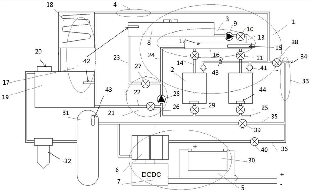
A continuous hydrogen generation device

A power generation device and hydrogen generation technology, applied in circuits, fuel cells, electrical components, etc., can solve problems such as potential safety hazards, large hydrogen generation devices, and inability to achieve continuous hydrogen production from solid hydrides

Active Publication Date: 2021-09-14
艾氢技术(苏州)有限公司
View PDF6 Cites 0 Cited by
  • Summary
  • Abstract
  • Description
  • Claims
  • Application Information

AI Technical Summary

Problems solved by technology

[0007] In the prior art hydrogen generation device, the metal hydride is put into the hydrogen generation device at one time, and then mixed with the liquid reactant (water), which has the following problems: 1. It is impossible to continuously add metal hydride to it during the hydrogen generation process. 2. The hydrogen production rate is slow, the utilization rate is low, and the reaction time is long; 3. Due to the need to accommodate more solid hydrides at one time, 4. It is not conducive to the industrialization of solid-state hydride hydrogen production in new energy vehicles and industrial fields; 5. The original hydrogen output system requires a more complicated control system, such as temperature control and pressure control. There are many requirements. If an error occurs on the control system, there will be a large safety hazard, and the working status of the real-time product is also quite unstable.

Method used


Image

  • A continuous hydrogen generation device

Examples


Embodiment Construction

[0032] The following will clearly and completely describe the technical solutions in the embodiments of the present invention with reference to the accompanying drawings in the embodiments of the present invention. Obviously, the described embodiments are only some, not all, embodiments of the present invention. Based on the embodiments of the present invention, all other embodiments obtained by persons of ordinary skill in the art without making creative efforts belong to the protection scope of the present invention.

[0033] In the description of the present invention, it should be noted that the terms "upper", "lower", "inner", "outer", "front end", "rear end", "both ends", "one end", "another end" The orientation or positional relationship indicated by etc. is based on the orientation or positional relationship shown in the drawings, and is only for the convenience of describing the simplified description of the present invention, rather than indicating or implying that th...


PUM


Abstract

The invention relates to the technical field of designing a hydrogen power generation device, and discloses a continuous hydrogen generation power generation device, including a hydrogen generation system and a fuel cell power supply system. The hydrogen generation system includes a plurality of independent solid hydrogen storage devices and water supply units And the gas delivery unit, the water supply unit can only inject reaction water into one of the solid hydrogen storage devices at the same time and when the volume of reaction water in the solid hydrogen storage device is greater than the threshold value or the temperature in the solid hydrogen storage device is greater than the threshold value The reaction water is discharged. When the hydrogen flow rate in the solid hydrogen storage device is less than the power supply required by the fuel cell power supply system, the water supply unit pumps out the reaction water in the solid hydrogen storage device, and after the reaction of the raw materials in the solid hydrogen storage device is completed, The water supply unit supplies water to the next solid hydrogen storage device according to the power generation needs of the fuel cell power supply system. The present invention can continuously produce hydrogen to achieve the purpose of power generation.

Description

technical field [0001] The invention relates to the technical field of batteries, in particular to a continuous hydrogen generating power generation device. Background technique [0002] In recent years, the environmental problems of the earth have become increasingly serious, especially the CO emitted by automobile exhaust. 2 , CO, S compounds, etc., not only bring the greenhouse effect to the atmosphere, but also cause serious pollution to the atmosphere. New energy vehicles that replace internal combustion engine vehicles are attracting more and more attention, especially hydrogen fuel cell vehicles, which are known for their zero emissions and long battery life. [0003] As one of the methods of storing hydrogen, there is an occlusion alloy method. As an occlusion alloy method, since it does not need to store hydrogen in a special state such as ultra-high pressure and extremely low temperature, it not only has excellent characteristics of easy operation and high safety...

Claims


Application Information

Patent Timeline
Patent Type & Authority Patents(China)
IPC IPC(8): H01M8/04082H01M8/04089H01M8/065
CPCH01M8/04089H01M8/04201H01M8/065H01M2250/20Y02E60/50
Inventor 刘奕辰俞强小笠原亮宗春燕郭芳芳
Owner 艾氢技术(苏州)有限公司
Why Eureka
Try Eureka