Bending foot connector led lamp assembly machine and its matching assembly method

A technology of LED lamp group and LED lamp, which is applied in the direction of assembly/disassembly of contact parts, etc., can solve the problems of unfavorable automatic wiring welding operation, low production efficiency, small size of LED lamp, etc., so as to facilitate automatic wiring welding operation and reduce wiring Difficulty, the effect of ensuring that they are level with each other

Active Publication Date: 2021-09-24
GOLDENCONN ELECTRONICS TECH CO LTD
View PDF0 Cites 0 Cited by
  • Summary
  • Abstract
  • Description
  • Claims
  • Application Information

AI Technical Summary

Problems solved by technology

In the prior art, the assembly of LED lamps is usually done manually, which is time-consuming and labor-intensive, and the production efficiency is low; in addition, the size of LED lamps is small, which is not conducive to manual handling and operation, and its lamp legs are slender structure, has a low bending strength, therefore, in the process of inserting the lamp pin into the insulating plastic body, it is very easy to interfere with the first slot that matches it, resulting in its bending under force Occurs, which leads to the different lengths of the lamp pins after the LED lamp is assembled, which is not conducive to the subsequent automatic wiring and welding operation. Therefore, it is urgent for technicians to solve the above problems

Method used


Image

  • Bending foot connector led lamp assembly machine and its matching assembly method
  • Bending foot connector led lamp assembly machine and its matching assembly method
  • Bending foot connector led lamp assembly machine and its matching assembly method

Examples


Embodiment Construction

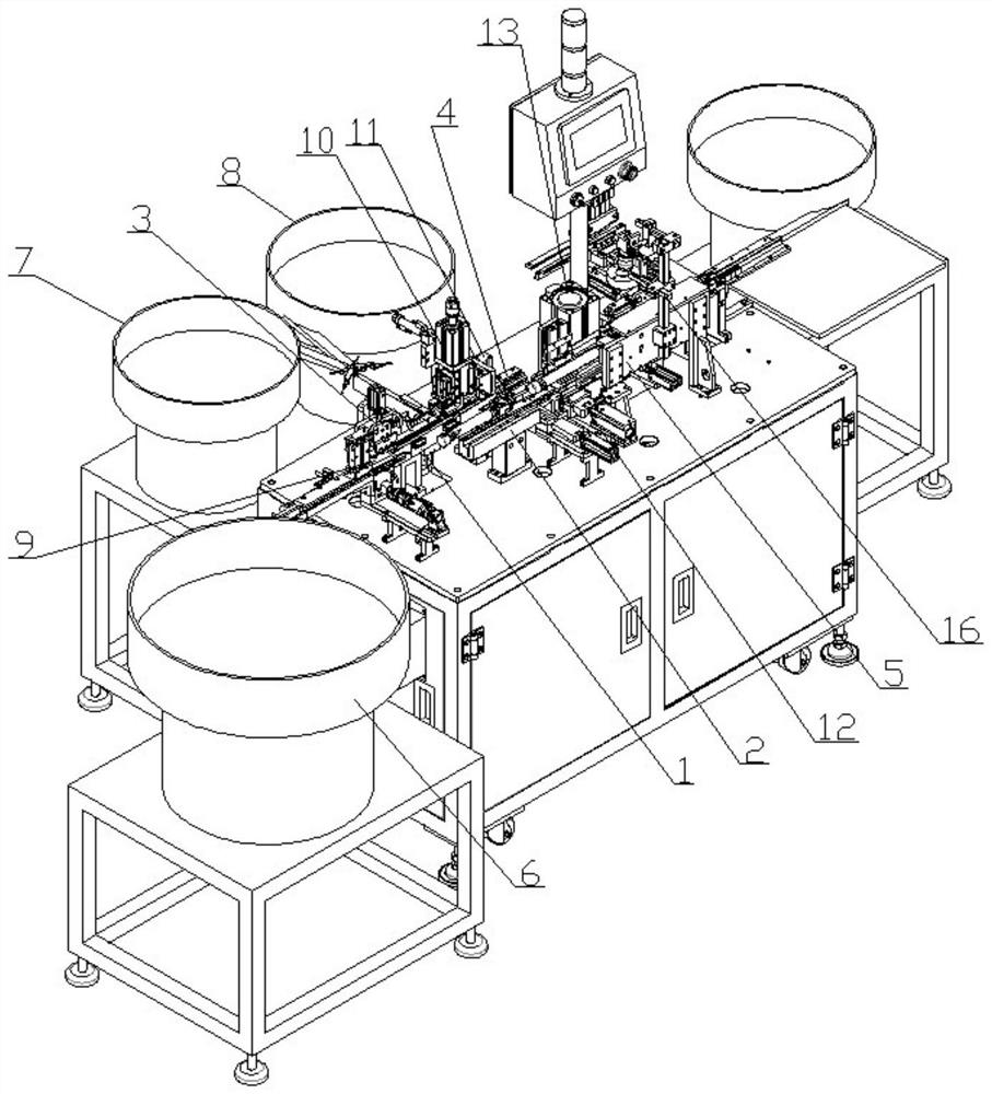
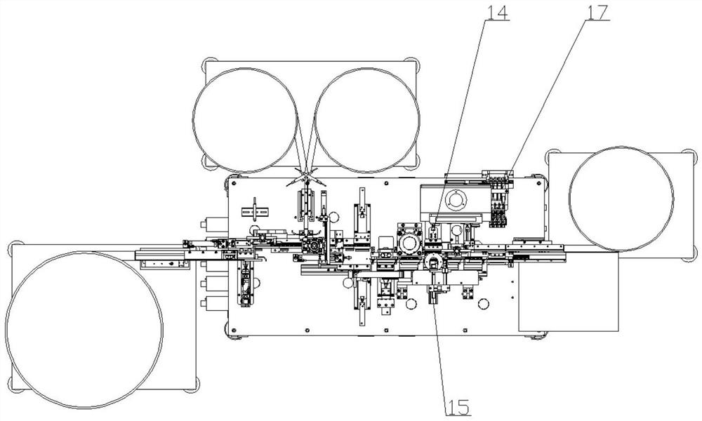
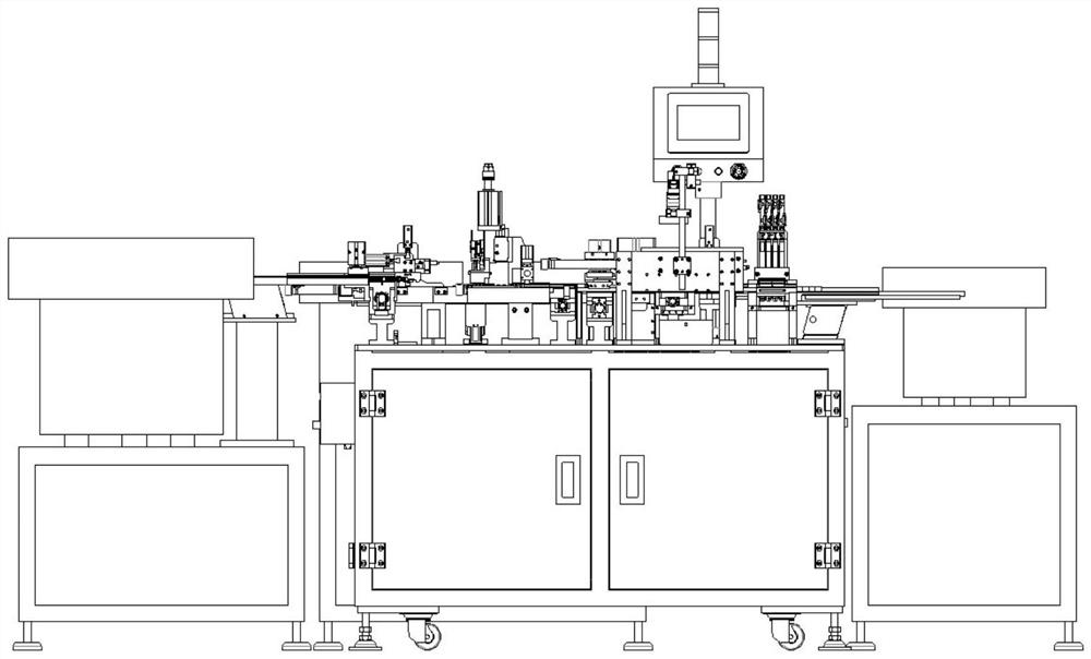
[0025] In order to make it easier for those skilled in the art to fully understand the technical solution disclosed in the present invention, before describing in detail the assembly machine of the bent-pin connector LED lamp, a general description of the structure of the bent-pin connector is given as follows: The connector is mainly composed of an insulating plastic body, a terminal block, a rear cover, a first LED light, and a second LED light. Wherein, along its width direction, a series of installation slots are arrayed on the bent pin connector. Before the official implementation of the assembly process of the LED lamp, the connection terminals are pre-inserted and fixed in the above-mentioned installation grooves. In addition, along its height direction, a first slot and a second slot are opened on the insulating plastic body for inserting the first LED lamp and the second LED lamp respectively. The first LED lamp is composed of a first LED lamp body and a first lamp p...


PUM


Abstract

The invention relates to an LED lamp assembly machine with bent pin connectors, thereby realizing automatic assembly of LED lamps, thereby improving assembly efficiency and reducing labor costs. The bent pin connector includes an insulating plastic body, a terminal block, a rear cover, a first LED light and a second LED light. A first slot and a second slot are opened on the insulating plastic body. The first LED lamp is composed of a first LED lamp body and a first lamp pin. The second LED lamp is composed of a second LED lamp body and a second lamp pin. The forming method of the bent pin connector includes the following steps: A. Inserting the first LED lamp and the second LED lamp into the first slot and the second slot respectively; B. Pressing down the first LED lamp and the second LED lamp at the same time lamp; C. 90° bending of the first lamp pin and the second lamp pin; D. cutting of the free ends of the first lamp pin and the second lamp pin. In this way, it is ensured that the lamp pins are flush with each other, thereby reducing the difficulty of subsequent wiring.

Description

technical field [0001] The invention relates to the technical field of electrical connector assembly, in particular to an LED lamp assembly machine with bent-pin connectors and an assembly method adapted thereto. Background technique [0002] The curved pin connector is used for the termination of the data cable to realize the connection and change between the equipment and the distribution frame module. It is known that the bent pin connector includes an insulating plastic body, a connection terminal, a rear cover, a first LED light and a second LED light. A first slot and a second slot are opened on the insulating plastic body for respectively inserting the first LED lamp and the second LED lamp. The first LED lamp is composed of a first LED lamp body and a first lamp pin. The second LED lamp is composed of a second LED lamp body and a second lamp pin. In the prior art, the assembly of LED lamps is usually done manually, which is time-consuming and labor-intensive, and ...

Claims


Application Information

Patent Timeline
Patent Type & Authority Patents(China)
IPC IPC(8): H01R43/20
CPCH01R43/20
Inventor 陈进嵩郭海洋
Owner GOLDENCONN ELECTRONICS TECH CO LTD
Why Eureka
Try Eureka