Stator and rotor assembling equipment in new energy motor assembly

A new energy, stator and rotor technology, applied in the manufacture of stator/rotor body, etc., can solve the problems of low assembly quality and assembly efficiency, difficult to ensure assembly coaxiality requirements, easy to damage the stator and rotor walls, etc., and achieve high assembly efficiency. , Improve assembly quality and assembly efficiency, the effect of compact structure layout

Active Publication Date: 2017-02-22
ANHUI JEE AUTOMATION EQUIP CO LTD
View PDF4 Cites 13 Cited by
  • Summary
  • Abstract
  • Description
  • Claims
  • Application Information

AI Technical Summary

Problems solved by technology

However, during the assembly process of the stator and rotor, due to the influence of the magnetic force between the stator and the rotor, the stator and rotor walls are often easily damaged during the assembly process, and it is difficult to ensure the coaxiality requirements of the assembly, resulting in low assembly quality and assembly efficiency.

Method used


Image

  • Stator and rotor assembling equipment in new energy motor assembly
  • Stator and rotor assembling equipment in new energy motor assembly
  • Stator and rotor assembling equipment in new energy motor assembly

Examples


Embodiment Construction

[0033] The embodiments of the present invention are described in detail below. This embodiment is implemented on the premise of the technical solution of the present invention, and detailed implementation methods and specific operating procedures are provided, but the protection scope of the present invention is not limited to the following implementation example.

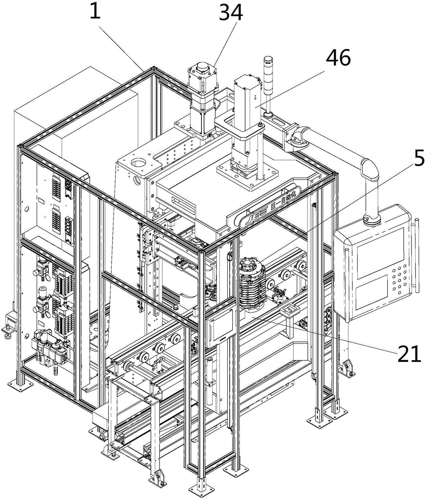
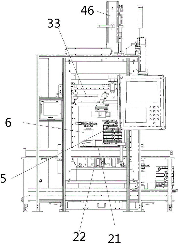
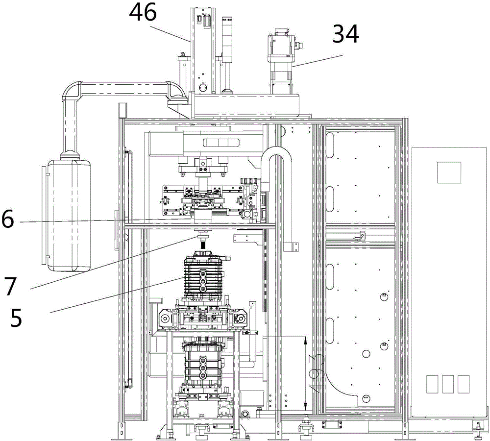
[0034] see Figure 1 to Figure 7 , this embodiment discloses a stator-rotor combination equipment for new energy motor assembly, including a fuselage 1, which is respectively provided with a double-layer lifting and positioning mechanism, a rotor clamping and shifting mechanism, a stator 5 clamping mechanism, and a pressing mechanism. installation mechanism.

[0035] The double-layer lifting and positioning mechanism includes a movable tray 21 and a fixed bottom plate 22 arranged up and down. The four corners of the lower end of the movable tray 21 are provided with guide rods 23, and the four corners of the upper...


PUM


Abstract

The invention discloses stator and rotor assembling equipment in the new energy motor assembly. The stator and rotor assembling equipment comprises a machine body, wherein a double-layer lifting positioning mechanism, a rotor clamping displacement mechanism, a stator tight holding mechanism and a press mounting mechanism are arranged on the machine body; wherein the double-layer lifting positioning mechanism comprises a movable tray and a fixed bottom plate in vertical arrangement; a rotor installing position and a stator installing position are arranged in parallel on the movable tray; the rotor lamping displacement mechanism comprises a vertical sliding installing seat, a transverse sliding installing seat and a holding claw assembly; the press mounting mechanism comprises a press head and an upper center; the upper center is vertically arranged in a cavity of the center of the press head; the upper part of the upper center is provided with an annular position limiting lug boss; the upper end of the upper center is provided with a spring in a sleeving way. The stator and rotor assembling equipment has the advantages that the upper end and the lower end of the rotor are simultaneously jacked by the upper center and the lower center to do synchronous descending along with the press head through being driven by an electric cylinder until the assembly is in place; the stator and rotor assembly concentricity is ensured; the influence of the magnetic force between the stator and the rotor on the assembly is overcome.

Description

technical field [0001] The invention relates to the technical field of motor assembly equipment, in particular to a stator-rotor assembly equipment for new energy motor assembly. Background technique [0002] The assembly of the stator and rotor of various new energy motors is usually carried out manually in the prior art and the rotor is manually assembled into the stator. However, during the assembly process of the stator and rotor, due to the influence of the magnetic force between the stator and the rotor, the stator and rotor walls are often easily damaged during the assembly process, and it is difficult to ensure the coaxiality requirements of the assembly, resulting in low assembly quality and assembly efficiency. Contents of the invention [0003] The purpose of the present invention is to overcome the deficiencies of the prior art and provide a new energy motor assembly stator and rotor assembly equipment, in order to achieve the purpose of greatly improving the a...

Claims


Application Information

Patent Timeline
Patent Type & Authority Applications(China)
IPC IPC(8): H02K15/02
CPCH02K15/02
Inventor 刘蕾赵学周何唯崔伟伟赵加佳
Owner ANHUI JEE AUTOMATION EQUIP CO LTD
Why Eureka
Try Eureka