
Multifunctional new energy solar device with greening structure

A solar device and multi-functional technology, applied in the direction of automatic watering devices, renewable energy machines, chemical instruments and methods, etc., can solve problems such as troublesome operation and affecting the absorption of solar light sources by silicon crystal plates, and achieve reasonable structure and functional combination good sex effect

Inactive Publication Date: 2020-08-07
新昌县云大农业有限公司
View PDF0 Cites 0 Cited by
  • Summary
  • Abstract
  • Description
  • Claims
  • Application Information

AI Technical Summary

Problems solved by technology

[0004] In order to solve the above-mentioned technical problems, the present invention provides a new energy solar device based on multi-function and greening structure, to solve the problem that when the existing generating set device of this type of structure is installed on the roof and used, after a period of time, the silicon crystal plate will be found There is a lot of dust on the surface. Because the dust adheres to the top of the silicon crystal plate, it will cause a certain shading effect on the silicon crystal plate, which will affect the normal absorption of solar light by the silicon crystal plate. Because some power generating units of this structure are installed on the roof, unlike the ground The type device can be conveniently wiped to remove dust, so that when the work is completed on schedule, there is no troublesome operation

Method used


Image

  • Multifunctional new energy solar device with greening structure
  • Multifunctional new energy solar device with greening structure
  • Multifunctional new energy solar device with greening structure

Examples


Embodiment

[0027] as attached figure 1 To attach Figure 8 Shown:

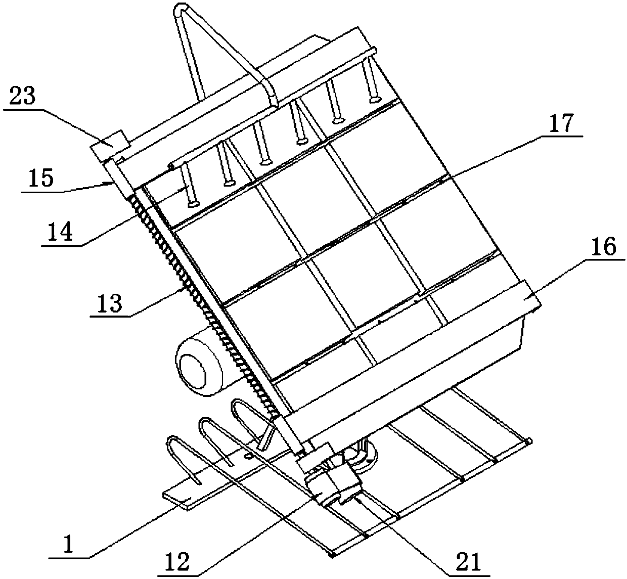
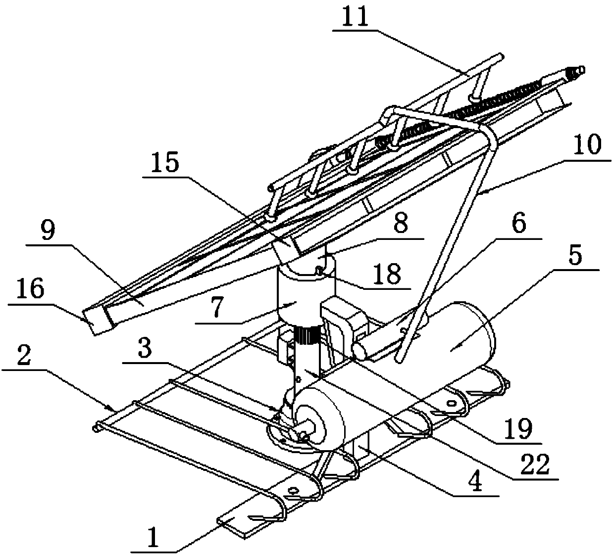
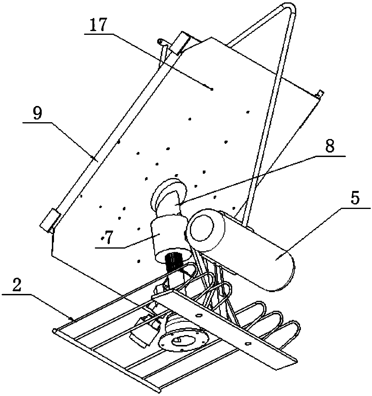
[0028] The present invention provides a new energy solar device based on multi-function and greening structure, including: a base plate 1, a placement frame 2, a reinforcement seat 3, a crutch 4, a water collection chamber 5, a pump 6, a sleeve 7, and an intubation tube 8 , power generation board group 9, upper water pipe 10, spray rack 11, conveyor belt 12, screw rod 13, nozzle 14, first wiper seat 15, second wiper seat 16, leakage hole 17, slide rail 18, air hole 19, electrical box 20, a servo motor 21, a column 22, a threading hole 2201 and a bearing seat 23; the reinforcement seat 3 is a seat structure, and a column 22 is vertically welded on its top surface, and a plug sleeve 7 is welded on the top surface of the column 22; The power generation board group 9 is inserted into the sleeve 7 through the intubation tube 8 at the bottom in an inclined manner, and a turning rod 4 with an L-shaped elbow structure is welde...


PUM


Abstract

The invention provides a new energy solar device based on multiple functions and provided with a greening structure. The new energy solar device comprises a sliding threading hole and a bearing seat,wherein a reinforcing seat is of a seat body structure, a stand column is perpendicularly welded to the top face of the reinforcing seat, an inserting sleeve is welded to the top face of the stand column, a power generation plate set is inserted into the inserting sleeve through an inserting pipe at the bottom in an inclined mode, a turning rod with an L-shaped bent pipe structure is welded to theouter side of the inserting sleeve in a welded mode, a bottom plate is welded on the bottom surface of the turning rod, a placement frame is further welded to the top surface of the bottom plate, a top spraying frame is used for carrying out cleaning and spraying treatment on a silicon crystal plate, two wiping seats are controlled by a reverse double thread to achieve simultaneous closing and opening so as to perform wiping and drying treatment on the surface of the silicon crystal plate subjected to water spraying treatment to achieve good function combinability, a welding frame used for storing plants is further arranged at the bottom, green plants can be placed on the frame, and water drips at the top are comprehensively utilized to achieve irrigation, so that the power generation setdevice of the environment-friendly greening structure is reasonable in structure.

Description

technical field [0001] The invention belongs to the technical field of generating set device structure, and more specifically relates to a new energy solar device based on multi-function and greening structure. Background technique [0002] The structure of the new energy generating set is mostly composed of the bottom welded support frame and the top silicon crystal plate group, as well as the power storage and control electrical components installed on the support frame related structure. Using the current core technology, the silicon plate installed on the top The crystal panel absorbs solar energy, converts solar energy into electrical energy through technical means, and finally collects electrical energy utilization technical means into energy storage electrical components. According to production or living needs, the converted electrical energy can be converted and utilized, playing a new role. The role of energy use. [0003] Based on the above description of the sil...

Claims


Application Information

Patent Timeline
Patent Type & Authority Applications(China)
IPC IPC(8): H02S40/10B08B3/02A01G27/02A01G27/00
CPCA01G27/003A01G27/02B08B3/02H02S40/10Y02E10/50Y02P60/12
Inventor 沈涛洋
Owner 新昌县云大农业有限公司
Learn More