Water spraying assembly special for dish washing machine
A dishwasher and component technology, which is applied to the parts of the dishwasher/rinsing machine for tableware, the washing machine/rinsing machine for tableware, applications, etc., can solve the problems of slow cleaning speed, consumption, low impact force, etc. The effect of increased surface, reduced washing time, and reduced impact force
- Summary
- Abstract
- Description
- Claims
- Application Information
AI Technical Summary
Problems solved by technology
Method used
Image
Examples
Embodiment 1
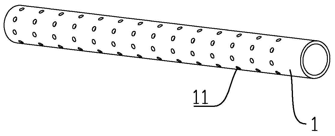
[0043] Such as figure 1 and figure 2Shown: a special water spray assembly for dishwashers, including a tubular water outlet pipe 1 with several water outlet holes 11 on the side wall, the water direction at the water outlet holes 11 is perpendicular to the center line of the water outlet pipe 1, and one end of the water outlet pipe 1 Airtight, and the other end is open; the water spray assembly also includes an adjustment mechanism that controls the swing of the outlet pipe 1; 3, and the driving part 4 which is connected with the other end of the inner sleeve body 2 and rotates by water flow. The inner sleeve body 2 includes a connecting pipe 21 (threaded connection may be used) connected at one end to the open end of the water outlet pipe 1, a directional inner casing with one end fixedly connected to the other end of the connecting pipe 21, and one end fixed to the other end of the directional inner casing. Connected contact tube; the connecting tube 21 communicates with ...
Embodiment 2
[0057] The difference between this embodiment and embodiment 1 is: see Figure 6 , Figure 9 , Figure 11 and Figure 12 As shown, the direction inner shell is the direction inner shell b22b, and the direction inner shell b22b includes a spherical shell-shaped wall and two symmetrical circular walls arranged parallel to each other on the spherical shell-shaped wall. Between the connecting pipe 21 and the direction inner shell b22b; the direction shell is a spherical shell type direction shell b31b, and the shape of the direction shell b31b corresponds to the direction inner shell b22b; the contact tube is an elliptical tube type contact tube b23b , that is, the contact tube b23b includes two opposite arc-shaped walls in contact with the contact wheel 44 and two opposite flat walls, and the flat wall surfaces are parallel to the circular wall surfaces; a spring 24 is connected to the outer side wall of the contact tube b23b , the spring 24 is located between the direction in...
Embodiment 3
[0060] The difference between this embodiment and embodiment 1 is: see Figure 7 , Figure 8 and Figure 13-Figure 15 As shown, the contact tube is a cross-section contact tube c23c, and the wall surface on the outer wall of the contact tube c23c corresponding to the four ends of the cross and contacting the contact wheel 44 is an arc-shaped wall; the outer wall of the contact tube c23c is connected with At least one spring 24, this spring 24 is between the direction inner shell a22a and the contact wheel 44, one end of this spring 24 is connected with the outer wall of the contact tube c23c (preferably connected with the arc wall of the contact tube c23c), and the other end is connected with the accommodating The inner wall of the tube 32 is connected. In this embodiment, the contact pipe 1 is pushed upwards, leftwards, downwards, rightwards and finally upwards (upwards, rightwards, downwards, leftwards and finally upwards) in sequence under the contact extrusion of the con...
PUM
 Abstract
Description
Claims
Application Information
 - R&D
- Intellectual Property
- Life Sciences
- Materials
- Tech Scout
- Unparalleled Data Quality
- Higher Quality Content
- 60% Fewer Hallucinations
Browse by: Latest US Patents, China's latest patents, Technical Efficacy Thesaurus, Application Domain, Technology Topic, Popular Technical Reports.
© 2025 PatSnap. All rights reserved.Legal|Privacy policy|Modern Slavery Act Transparency Statement|Sitemap|About US| Contact US: help@patsnap.com


