Optical adjustment platform for quantum optical test

A technology of optical adjustment and quantum optics, which is applied in the direction of laboratory stools/lab tables, educational appliances, teaching models, etc., can solve the problems of insufficient portability, optical lenses can only be adjusted in one dimension, and the adjustment direction is limited, so as to achieve convenience The effect of folding and carrying

Active Publication Date: 2020-08-11
CHANGCHUN UNIV OF SCI & TECH +1
View PDF6 Cites 2 Cited by
  • Summary
  • Abstract
  • Description
  • Claims
  • Application Information

AI Technical Summary

Problems solved by technology

[0004] The invention proposes an optical adjustment platform for quantum optics experiment, which solves the problem that the existing optical experiment adjustment platform is not portable enough, and the direction of the optical lens can only be adjusted one-dimensionally, resulting in limited adjustment direction.

Method used


Image

  • Optical adjustment platform for quantum optical test
  • Optical adjustment platform for quantum optical test
  • Optical adjustment platform for quantum optical test

Examples


Embodiment 1

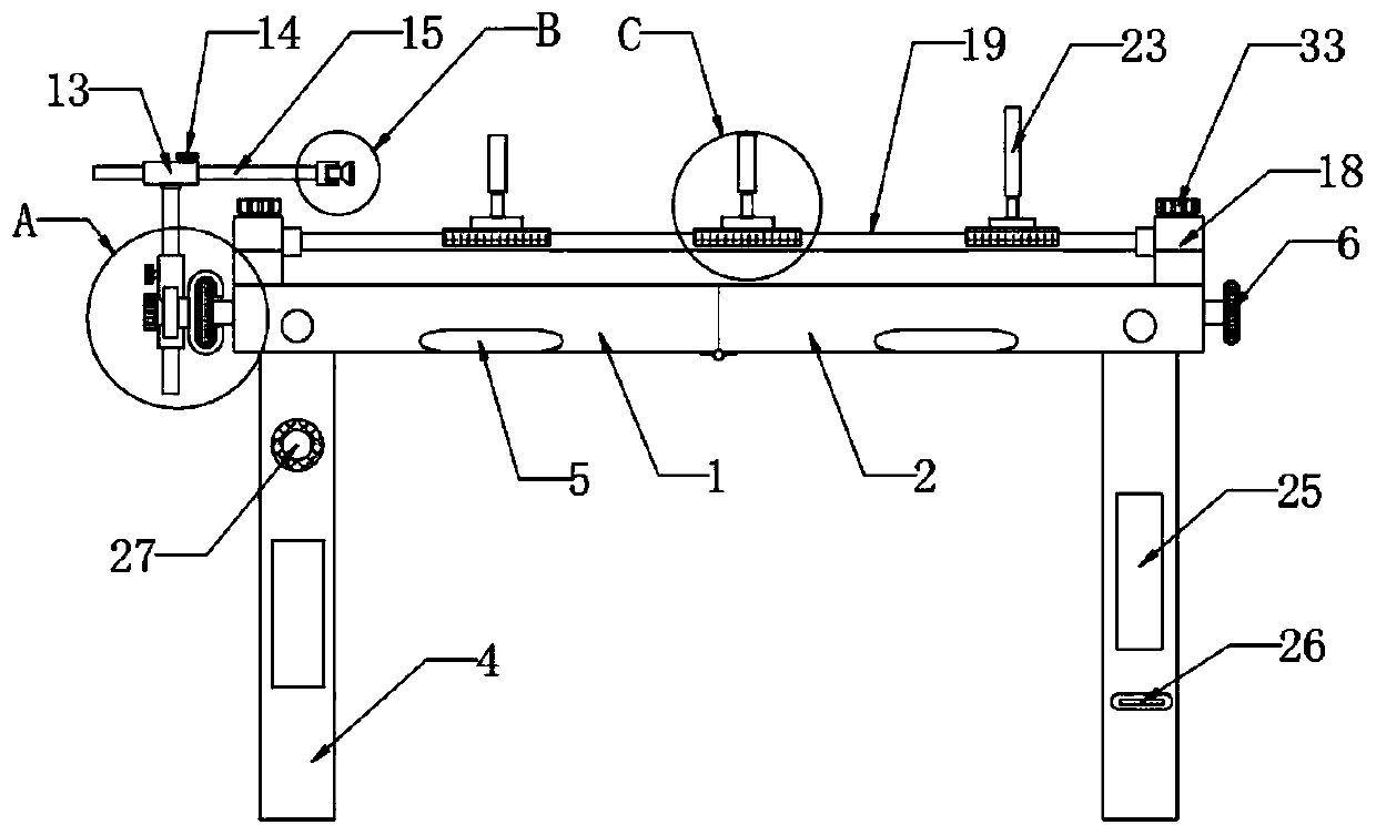
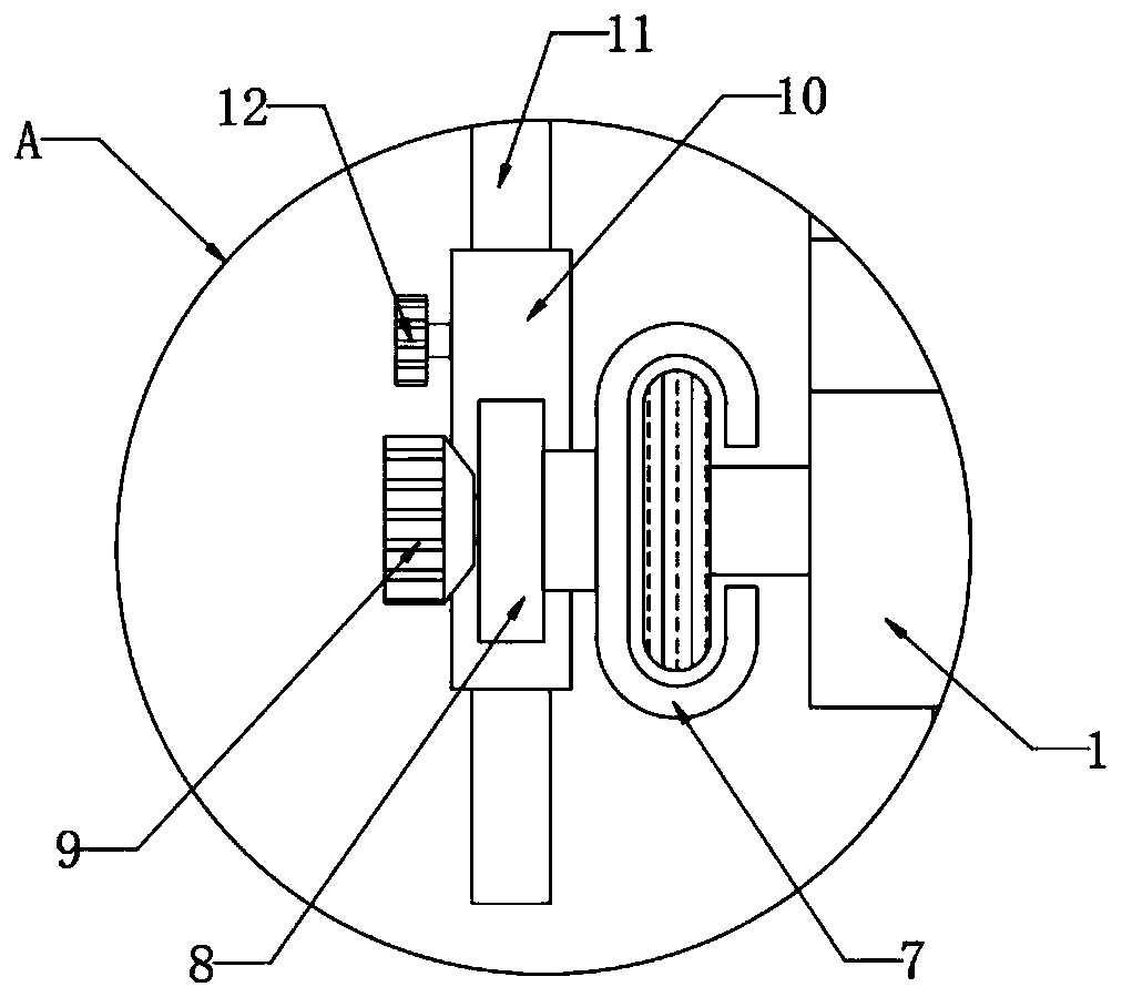
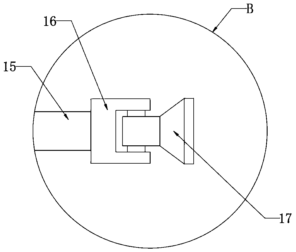
[0030] Embodiment 1: When the device is in use, first slide the adjustment slider 7 along the length direction of the adjustment slide rail 6 to adjust the position of the light source lamp 17 on the side of the test bench, and then slide along the length direction of the lifting sleeve 10 Adjust the lifting rod 11 so that the light source lamp 17 moves up and down with the lifting rod 11, thereby adjusting the height of the light source lamp 17 to a suitable position, and then rotate the first locking bolt 12 so that the lifting rod 11 is opposite to the lifting sleeve 10 Fix, then turn the level adjustment sleeve 13, so that the level adjustment sleeve 13 drives the level adjustment rod 15 to rotate to adjust the horizontal irradiation angle of the light source lamp 17, then slide the level adjustment rod 15 along the length direction of the level adjustment sleeve 13 , and the light source lamp 17 moves along with the horizontal adjustment rod 15, so as to reach the horizont...

Embodiment 2

[0031] Embodiment 2: By extracting the adjusting rod seat 18 from the inside of the mounting hole 24, then removing the adjusting rod 19 from the adjusting rod seat 18, and removing the lens seat 20 from the adjusting rod 19, by pulling the adjusting rod seat 18. Put the adjustment rod 19 and the lens holder 20 into the storage tank 3 to complete the storage of the adjustment rod holder 18, the adjustment rod 19 and the lens holder 20; And the horizontal adjusting rod 15 is taken off from the adjusting slide rail 6, then the first locking bolt 12 and the second locking bolt 14 are rotated, so that the lifting rod 11 and the horizontal adjusting rod 15 are separated from the lifting sleeve 10 and the horizontal adjusting sleeve respectively. The inside of the cylinder 13 is separated, and the fixing plate 8, the lifting sleeve 10, the level adjusting sleeve 13, the lifting rod 11 and the level adjusting rod 15 are all put into the inside of the storage tank 3, and the fixing pla...


PUM


Abstract

The invention discloses an optical adjustment platform for a quantum optical test, which relates to the technical field of optical test equipment. The problem that an existing optical test adjusting platform is not portable enough, the direction of the optical lens can only be adjusted in one dimension, and the adjustment direction is limited is solved. Proposed now is the following scheme, the platform comprises a first test bench, a fixing plate, a battery, an adjusting rod seat and a second test bench. The first test bench and the second test bench are hinged to each other. The lower surface of the first test bench and the lower surface of the second test bench are each provided with a storage groove, the two storage grooves are symmetrically distributed, supporting legs which are evenly distributed are rotationally installed on the inner walls of the storage grooves, and the supporting legs are located at the corners of the first test bed and the second test bed respectively. Theplatform has the function of being convenient to fold and carry, and the irradiation height, the horizontal position and the angle of the light source lamp can be conveniently adjusted; meanwhile, theposition of the lens and the imaging position of an imaging plate are convenient to adjust.

Description

technical field [0001] The invention relates to the technical field of optical test equipment, in particular to an optical adjustment platform for quantum optical tests. Background technique [0002] Optical experiment is an important way to conduct experimental research on light interference, diffraction, polarization, etc., and the knowledge of light can be popularized through optical experiments. In order to better perform optical experiments, we often need optical experiment adjustment platforms, so that Perform lens and imaging plate adjustments. [0003] The existing optical test adjustment platforms often have a relatively simple structure and relatively simple functions. The current optical test adjustment platform is slidably connected to the adjustment rod through the lens seat, and the adjustment rod and the base are fixedly connected, so that the lens can only be moved along the The direction of the adjustment rod is adjusted within a one-dimensional range, and ...

Claims


Application Information

Patent Timeline
Patent Type & Authority Applications(China)
IPC IPC(8): B01L9/02G09B23/22
CPCB01L9/02G09B23/22
Inventor 林宏宇姚治海王晓茜
Owner CHANGCHUN UNIV OF SCI & TECH
Why Eureka
Try Eureka