
Circular rubber pad cutting device

A rubber pad and circular technology, which is applied in the field of circular rubber pad interception devices, can solve the problems of slow rubber pad interception, rubber pad stuck in the mold, rubber sheet cannot be delivered on time, etc., to improve Utilization rate and the effect of reducing leftovers

Active Publication Date: 2020-08-11
无锡市西海科技有限公司
View PDF6 Cites 7 Cited by
  • Summary
  • Abstract
  • Description
  • Claims
  • Application Information

AI Technical Summary

Problems solved by technology

[0004] The object of the present invention is to provide a kind of can carry out fast pressing interception to rubber sheet, obtain the circular rubber pad of precise size, the circular rubber pad intercepting device of convenient collection rubber pad after intercepting, to solve the existing problem that proposes in above-mentioned background technology The mold pressing device is inconvenient to collect after pressing, and it needs to be collected manually. The rubber pad will be stuck in the mold, and it is inconvenient to take it out manually. The problem of slow interception

Method used


Image

  • Circular rubber pad cutting device
  • Circular rubber pad cutting device
  • Circular rubber pad cutting device

Examples


Embodiment 1

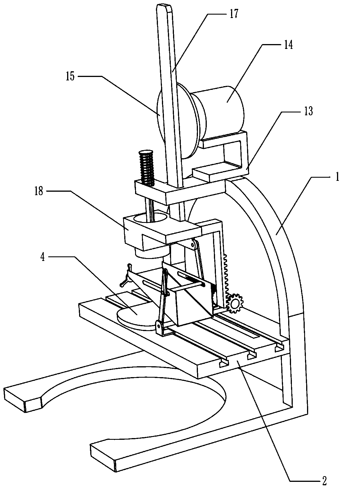
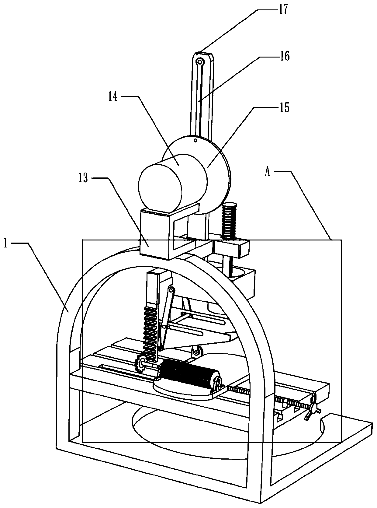
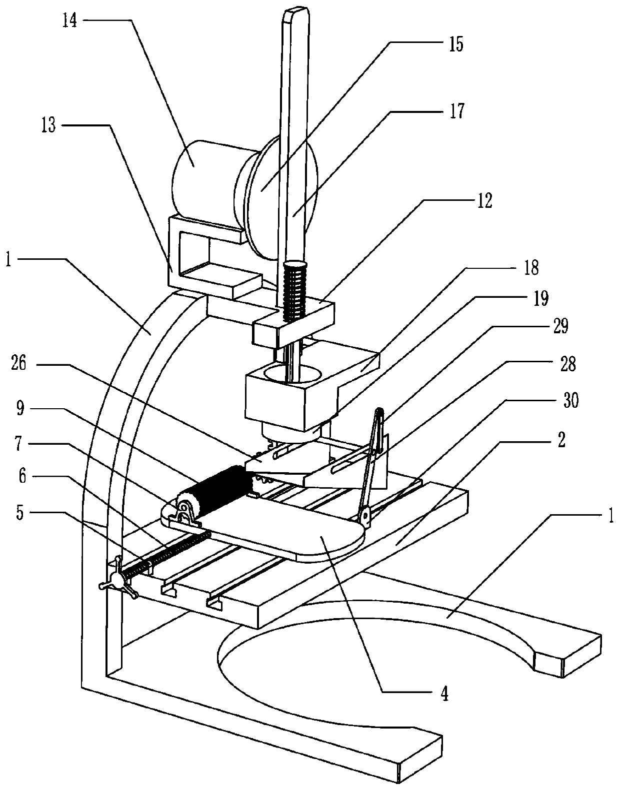
[0023] A circular rubber mat intercepting device such as Figure 1-7 As shown, it includes outrigger 1, slide rail 2, slider 3, support plate 4, fixed seat 7, fixed plate 12, support seat 13, motor 14, turntable 15, transmission connecting rod 16, guide rod 17, hollow Plate 18, circular cutter 19, rack 20, adjustment mechanism and transmission mechanism, the slide rail 2 is fixedly installed on the leg 1 and has three slideways, and the three slide blocks 3 are slidably installed on the slide On the rail 2, the support plate 4 used to place the raw material of the rubber sheet is fixedly installed on the slider 3, and the two fixed seats 7 are fixedly installed on the upper side of the support plate 4, and are arranged symmetrically. The fixed plate 12 The rear end is fixedly installed on the front side of the leg 1 and above the support plate 4, the support seat 13 which plays a supporting role is fixedly installed on the leg 1 and is located on the upper side of the fixed pl...

Embodiment 2

[0025] On the basis of Example 1, such as Figure 1-7 As shown, the adjustment mechanism includes a nut 5 and a screw rod 6, the nut 5 is fixedly installed on the slide rail 2 and is located on the left side of the support plate 4, the screw rod 6 is sleeved in the nut 5, and the right end of the screw rod 6 is connected to the support plate The left side of the plate 4 is rotationally connected, and the operator can adjust the position of the support plate 4 by rotating the screw 6 .

[0026] After the work of cutting a circular rubber pad is completed, the transmission mechanism that can transmit the raw material of the rubber sheet forward includes a rotating shaft 8, a transmission wheel 9, an overrunning clutch 10 and a gear 11. The rotating shaft 8 is rotatably installed on two fixed On the seat 7, and the right end of the rotating shaft 8 passes through the fixed seat 7 close to the rack 20, and the transmission wheel 9, which plays the role of transmitting the raw mate...

specific Embodiment approach

[0029] Specific implementation method: when it is necessary to cut a whole piece of rubber sheet into several circular rubber pads, first place the rubber sheet on the support plate 4 manually, and adjust the position of the support plate 4 through the adjustment device to make the rubber sheet move to the right To the circular cutter 19 below.

[0030]Then manually turn on the motor 14 to rotate clockwise, which drives the rotating disk 15 to rotate clockwise. Under the action of the transmission connecting rod 16, the guide rod one 17 is moved downward, and the hollow plate 18 fixedly connected with the guide rod one 17 lower ends also moves downward. , the circular cutter 19 moves downward with the hollow plate 18, and at the same time the rack 20 fixedly connected to the rear side of the hollow plate 18 moves downward, and the gear 11 meshing with the rack 20 rotates counterclockwise, but when the overrunning clutch 10 Under action, gear 11 can not drive transmission wheel...


PUM


Abstract

The invention relates to the technical field of rubber processing, in particular to a circular rubber pad cutting device. The invention aims at solving the technical problem so as to provide the circular rubber pad cutting device capable of quickly pressing and cutting a rubber sheet, obtaining a circular rubber pad with the accurate size, and conveniently collecting the cut rubber pad. The invention provides the following technical scheme that the circular rubber pad cutting device comprises a support leg, a slide rail, sliding blocks, a support plate, a fixed seat, a fixed plate, a support seat, a motor, a rotary plate, a transmission connecting rod, a guide rod I, a hollow plate, a circular cutter and the like, wherein the slide rail is fixedly arranged on the support leg; a plurality of sliding blocks are slidably arranged on the slide rail; and the support plate is fixedly arranged on the sliding blocks. According to the circular rubber pad cutting device provided by the invention, the position of the support plate can be adjusted through manually rotating a screw rod, so that the circular cutter can be used for cutting the circular rubber pad at different positions in the horizontal direction of the rubber sheet, and the rubber sheet utilization rate is improved.

Description

technical field [0001] The invention relates to the technical field of rubber processing, in particular to a circular rubber pad cutting device. Background technique [0002] There are generally two ways of making rubber mats: cutting and molding. The cutting method is to use a gasket cutting machine or a rubber pad cutter to cut and shape a whole piece of rubber sheet, but the utilization rate of the rubber sheet is not very high, and at present, when the rubber pad cutter cuts a thin rubber pad, the rubber pad It is easy to bulge or sink, which makes the cutting size deviate, and it is impossible to get a more accurate round rubber pad. [0003] The molding method is to use a specific mold to press the rubber sheet to obtain a rubber pad of a specific shape. Compared with the cutting method, the molding method is more material-saving, and a precise circular rubber pad can be obtained by pressing a circular mold. The existing The mold pressing device is inconvenient to co...

Claims


Application Information

Patent Timeline
Patent Type & Authority Applications(China)
IPC IPC(8): B26F1/40B26D5/08B26D7/32B26D7/20
CPCB26D5/083B26D7/20B26D7/32B26D2007/206B26F1/40
Inventor 陈建生
Owner 无锡市西海科技有限公司
Learn More