Hinge lock

A technology of chain locks and hinges, applied in the field of hinge locks, can solve the problems of less combined use of handle locks and hinge devices, lack of sliding plate locks, etc., and achieve the effects of good linkage effect, convenient production and reasonable structure design.

Active Publication Date: 2020-08-11
宁波生久科技有限公司
View PDF7 Cites 2 Cited by
  • Summary
  • Abstract
  • Description
  • Claims
  • Application Information

AI Technical Summary

Problems solved by technology

[0003] In order to overcome the above-mentioned shortcomings, the purpose of the present invention is to provide a hinge lock in the art, so that it solves the problem that existing similar handle locks and hinge devices are rarely used in combination, and the handle lock and similar products lack slide plate locking in the locking groove. And the technical problems of internal opening structure design

Method used


Image

  • Hinge lock
  • Hinge lock
  • Hinge lock

Examples


Embodiment Construction

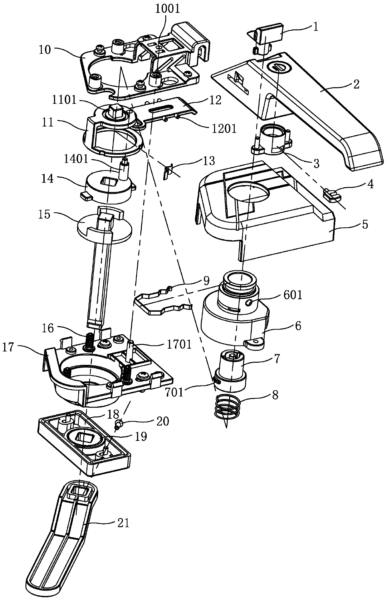
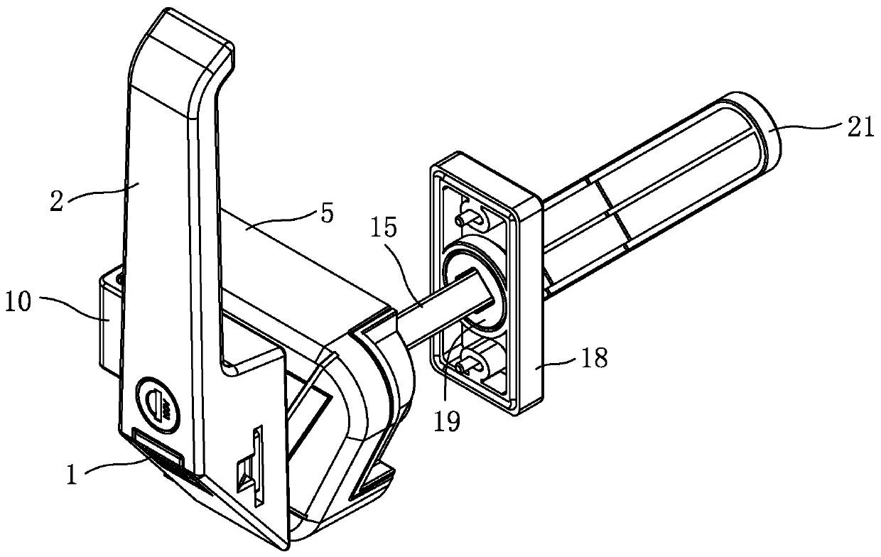
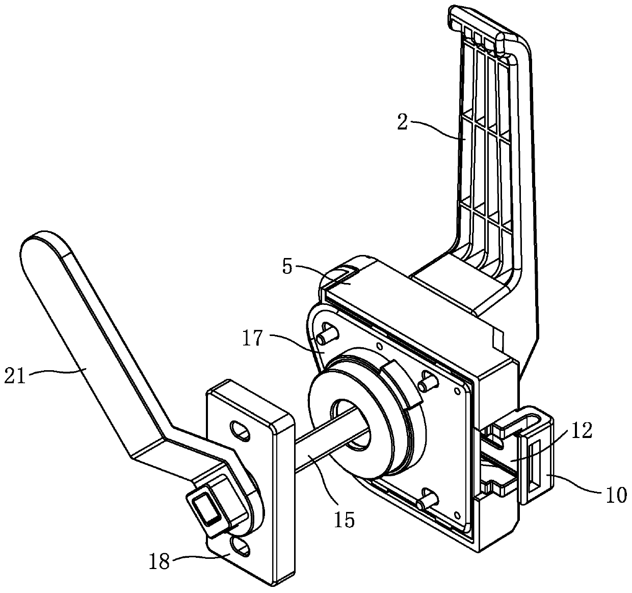
[0024] Now in conjunction with the accompanying drawings, the structure and use of the present invention will be further described. like Figure 1-Figure 8 As shown, one side of the lock body of the hinge lock is provided with a handle 2, and the handle is provided with a lock cylinder assembly, and the bottom of the lock cylinder assembly is encapsulated in the handle through a steel bolt sleeve 3, and the lock head at the bottom of the lock cylinder assembly and the special-shaped steel bolt 4 One end of the lock sleeve 6 protruding from the cover 5 is inserted into the handle, and the other end of the special-shaped steel bolt is inserted into the outer hole 601 of the outer diameter of the lock sleeve in the handle through the arc-shaped side hole of the steel bolt sleeve. The outer diameter is provided with a ring groove, and the circlip 9 is inserted from one side of the handle and snapped and fixed in the ring groove of the lock sleeve, and the lock sleeve and the handl...


PUM


Abstract

The invention relates to a hinge lock, and is designed for aiming at the technical problems that existing similar handle locks and hinge devices are rarely combined for use, and sliding plate lockingis lacked in locking grooves in similar products. A lock cylinder assembly is arranged on a handle on one side of a lock body of the hinge lock, the bottom of the lock cylinder assembly is packaged inthe handle through a steel bolt sleeve, a lock head at the bottom of the lock cylinder assembly is connected with one end of a special-shaped steel bolt, one end, extending out of a cover, of a locksleeve is inserted into the handle, the lock sleeve and the handle are connected into a whole; the other end of the lock sleeve is fixed to a sliding rail on a bottom plate, the sliding rail is fixedto the bottom plate, a sliding block is arranged on the bottom plate in a lower cavity of the lock sleeve, one end of a sliding plate in the sliding block is inserted into the sliding block and the lock sleeve, meanwhile, the sliding plate is connected with the sliding block and slides through oblique sliding holes in the two sides, the other end of the sliding plate extends out of a locking opening with one side open of the cover; and a square table at the top of the sliding block is sleeved with one end of a tool lock cylinder in an upper cavity of the lock sleeve, and a tool key of the handle is inserted and fixed into a corresponding tool hole in the top of the tool lock cylinder through protruding blocks on the two sides of the bottom.

Description

technical field [0001] The invention relates to a handle lock, which is a hinge lock with a handle. Background technique [0002] Handle lock is a product that operates the lock to unlock and close through the handle. The handle of this type of product can also be replaced by a knob-type handle structure, which generally includes handles, lock cylinders, bolts, shafts, bases and other components. Existing locks with handles, such as the application number 201811542426.4 disclosed in the Chinese patent literature, the application publication date is 2019.03.01, and the invention name is "electronic door lock device with high anti-theft performance"; existing hinge lock products, such as the Chinese patent literature The disclosed application number is 201710955099.4, the application publication date is 2018.04.10, and the title of the invention is "hinge locking device, locking device and rail vehicle door system". But above-mentioned handle lock or hinge device are more dif...

Claims


Application Information

Patent Timeline
Patent Type & Authority Applications(China)
IPC IPC(8): E05B15/00E05B3/00E05B63/00E05B65/06E05D7/00E05D11/00
CPCE05B15/00E05B3/00E05B63/00E05B65/06E05D7/00E05D11/00
Inventor 姚春良宁良发沈达立
Owner 宁波生久科技有限公司
Why Eureka
Try Eureka