Diversion structure of turbine low-pressure vapor inlet chamber, and parameter design method for same

A steam inlet chamber and steam turbine technology, which is applied in mechanical equipment, engine components, machines/engines, etc., can solve the problem of poor axial airflow stability and reliability, increased exhaust dynamic loss of axial flow blades, and inconsistent airflow angle at the chamber outlet. Uniformity and other issues to achieve the effect of reducing blade loss and work loss, reducing steam non-uniformity, improving stability and aerodynamic economy

Active Publication Date: 2020-08-11
DONGFANG TURBINE CO LTD
View PDF15 Cites 5 Cited by
  • Summary
  • Abstract
  • Description
  • Claims
  • Application Information

AI Technical Summary

Problems solved by technology

[0004] One is that the outlet airflow angle of the chamber is not uniform, and it is difficult to achieve a good match with the geometric angle of the downstream axial flow blade row, which will bring a large loss of angle of attack;
[0005] The second is that when the flow changes from radial to axial, it is more severe, and flow separation will occur at the tip of the stator blade, resulting in losses. That is, the two-way flow of air flow from radial to axial serves as the aerodynamic boundary condition of the downstream axial flow stage is unstable, resulting in poor stability and reliability of the axial flow entering the axial flow stage
At the same time, since the air flow does not achieve a good guide and transition in the process of changing from radial to axial, the axial air flow after two-way splitting forms a vortex when it enters the downstream axial flow blade row, causing the axial flow blade to discharge into the inlet. Inhomogeneity of the air flow, which in turn causes high losses, increasing the aerodynamic losses of the row of axial blades
[0006] In addition, the direct impact of the airflow on the wheel rotor will also bring about the stability of the wheel rotor
[0007] Based on the above shortcomings, the traditional low-voltage design has economic and stability problems

Method used


Image

  • Diversion structure of turbine low-pressure vapor inlet chamber, and parameter design method for same
  • Diversion structure of turbine low-pressure vapor inlet chamber, and parameter design method for same
  • Diversion structure of turbine low-pressure vapor inlet chamber, and parameter design method for same

Examples


Embodiment 1

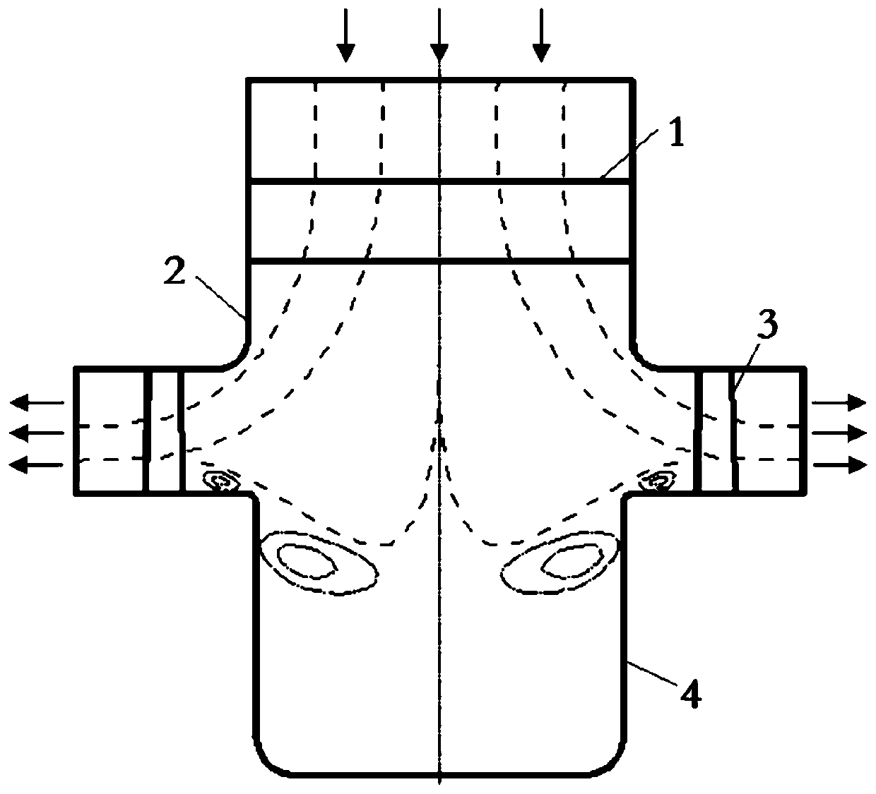
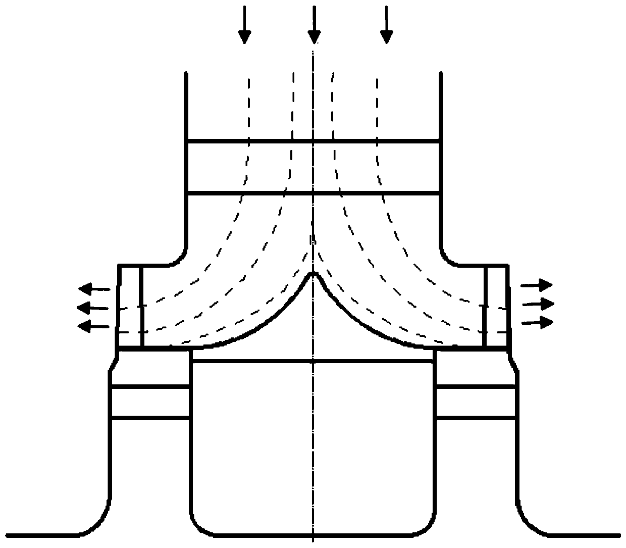
[0033] Such as figure 2 , image 3 As shown, in this embodiment, a flow diversion structure of a low-pressure steam inlet chamber of a steam turbine is specifically disclosed, including a steam inlet chamber 2, a wheel rotor 4, a first-stage vane 1 and two The sideways and symmetrically arranged first-stage moving blades 3 combine the intake chamber 2, the wheel rotor 4, the first-stage vane 1, and the first-stage moving blades arranged symmetrically on both axial sides of the wheel rotor 4 3 Assemble according to the corresponding technical specifications, such as figure 1 As shown, it is a traditional diversion structure of the low-pressure steam inlet chamber. Its working principle and structural composition have been explained in the background art, and will not be repeated here.

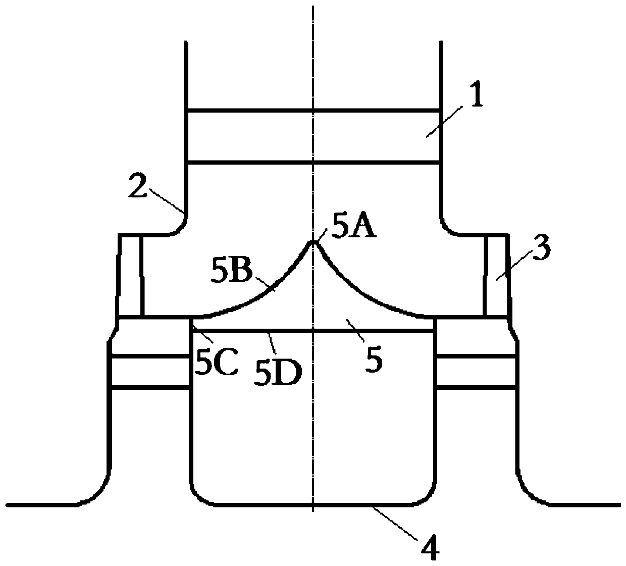
[0034] In order to further improve the diversion effect of the diversion structure of the low-pressure steam inlet chamber, a diversion structure is also included. The diversion structure is ...


PUM


Abstract

The invention discloses a diversion structure of a turbine low-pressure vapor inlet chamber and belongs to the technical field of turbines of thermal power, nuclear power and the like. The structure comprises a vapor inlet chamber room, a wheel type rotor, a first stage static blade and first stage movable blades which are disposed on two axial sides of the wheel type rotor and are arranged symmetrically. The diversion structure is also provided, wherein the diversion structure is concentrically disposed with the wheel type rotor. Symmetric bypass chambers are formed by the diversion structure, the vapor inlet chamber room, the first stage static blade and the first stage movable blades disposed on the two axial sides of the wheel type rotor; and by the bypass chambers, a flow direction ofan airflow which enters from the first stage static blade can be changed from a radial direction to an axial direction, and can realize symmetric bypassing to the first stage movable blades on the two axial sides. In this way, the radial direction of vapor is changed to the axial direction, so that diversion and stable transition are realized; and airflow uniformly in front of a blade row is enhanced.

Description

technical field [0001] The invention belongs to the technical field of steam turbines such as thermal power and nuclear power, and specifically relates to a flow diversion structure of a low-pressure steam inlet chamber of a steam turbine and a parameter design method thereof. Background technique [0002] The demand for energy in modern society continues to increase, and the comprehensive utilization of energy has also begun to receive greater attention. As a steam turbine, an important power equipment in a modern country, improving its economy is obviously of great significance to saving energy. With the change of the economic situation, the demand for the transformation of old units is becoming more and more urgent, and the transformation and technical innovation of the steam turbine inlet room are also an important part of it. [0003] After the traditional low-pressure air inlet chamber enters the air inlet chamber from the middle and low pressure connecting pipe, it f...

Claims


Application Information

Patent Timeline
Patent Type & Authority Applications(China)
IPC IPC(8): F01D9/02
CPCF01D9/02
Inventor 平艳钟主海江生科陶志坚张晓东陈阳杨长柱王娟丽
Owner DONGFANG TURBINE CO LTD
Why Eureka
Try Eureka