Glass light guide plate and production process thereof, and display device
A technology of glass light guide plate and production process, which is applied in the field of light guide plate, can solve the problems of high cost and low production yield, and achieve the effects of improving efficiency, saving process and cost, and having strong plasticity
Active Publication Date: 2020-08-11
冯宪轮
View PDF9 Cites 4 Cited by
- Summary
- Abstract
- Description
- Claims
- Application Information
AI Technical Summary
Problems solved by technology
Now the glass light guide plate + side direct light method is more and more widely used, but no matter what kind of material the light guide plate is, what kind of light source is incident, what can’t change is the upper and lower diffusion film, quantum dot film, light enhancement film The use of the upper and lower diffu
Method used
View moreImage
Smart ImageViewing Examples

Examples
 PUM
| Property | Measurement | Unit |
|---|---|---|
| Thickness | aaaaa | aaaaa |
| Thickness | aaaaa | aaaaa |
Abstract
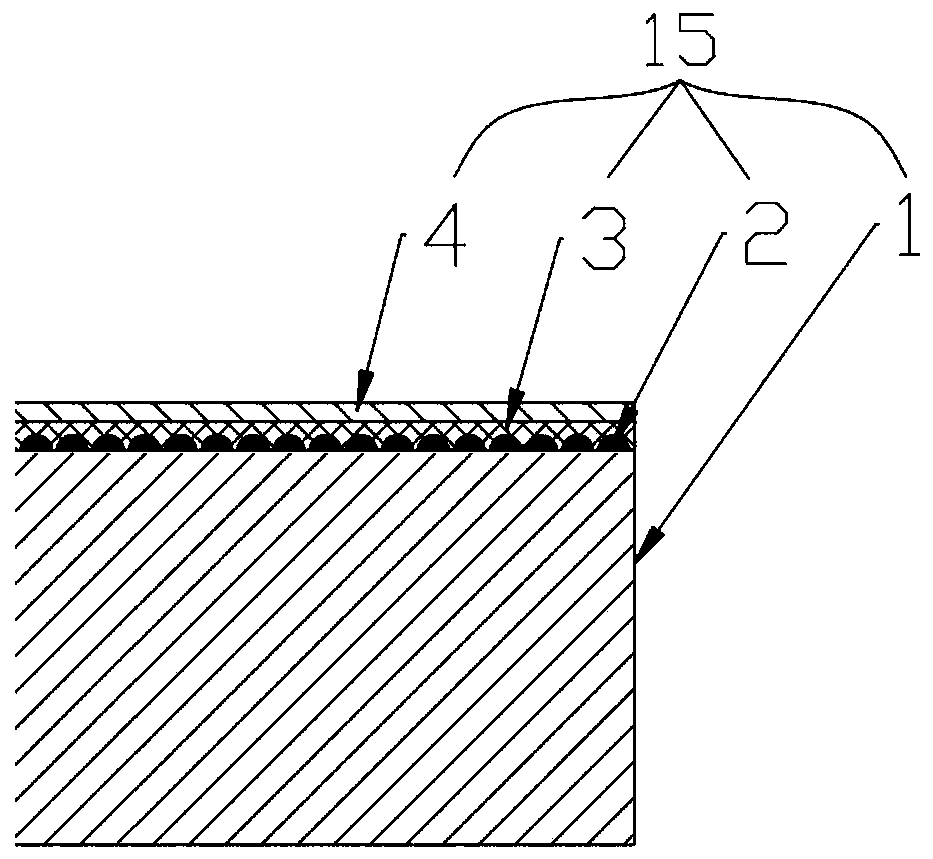
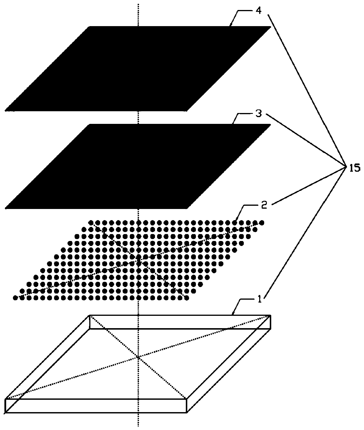
The invention relates to a glass light guide plate and a production process thereof, and a display device. The production process is characterized in that the glass being subjected to cold machining forming according to needs, and obtaining a glass blank; carrying out polishing treatment of the glass blank to obtain a glass substrate; preparing a nanoscale light guide ink layer with the thicknessof 10-30 [mu] m on a first surface of the glass substrate, then setting a light guide point negative film pattern on a UV laser machine, then exposing, and carving the nanoscale light guide ink layerinto a plurality of light guide points; taking a non-conductive silicon oxide material as a target material, and preparing a non-conductive colorless optical layer with the thickness of 50-100nm on asurface of the light guide point in a continuous magnetron sputtering coating manner; and preparing a UV reflecting layer on the surface of the non-conductive colorless optical layer to obtain the glass light guide plate. The production process is advantaged in that the light guide module is formed on the glass substrate, manufacturing, machining and assembling of the lower diffusion film, the brightness enhancement film and the upper diffusion film are omitted, procedures and cost are saved, and efficiency can be improved.
Description
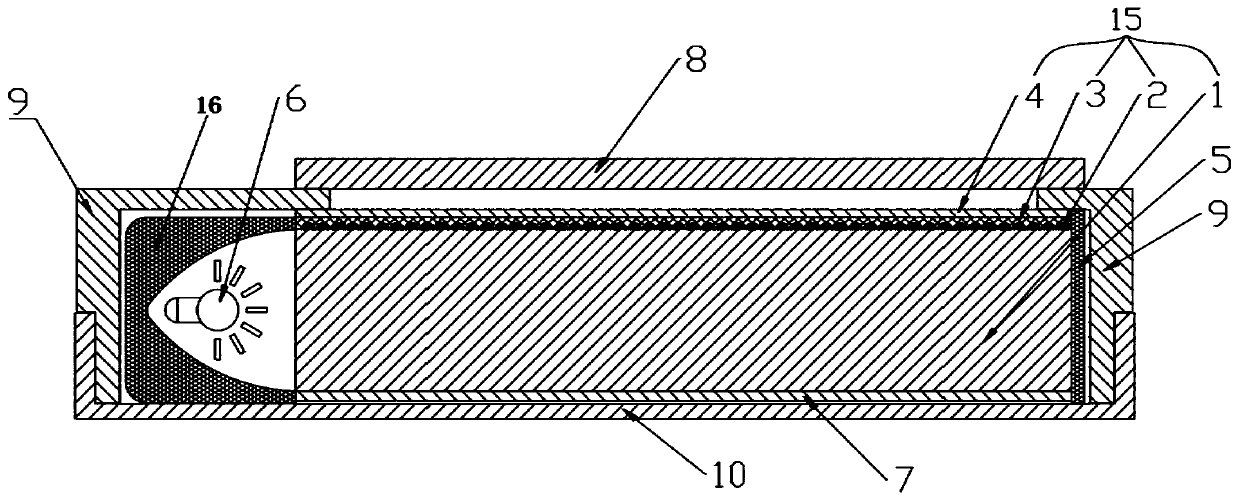
technical field [0001] The invention relates to a glass light guide plate, its production process and a display device, belonging to the field of light guide plates. Background technique [0002] Usually, the liquid crystal module is composed of a backplane + LED, a reflector, a light guide plate, a lower diffusion film, a quantum dot film, an enhancement film, an upper diffusion film, a guide frame and a liquid crystal panel. There are three modes of incidence of the light source: rear direct radiation, side oblique radiation and side direct radiation. The thickness of the liquid crystal module composed of the three methods is that the thickness of the rear direct radiation > the thickness of the side oblique radiation > the thickness of the side direct radiation. More and more manufacturers use the method of side direct radiation. The selected scheme. In the selection of the light guide plate, there are two choices of PMMA material and glass material. Due to the def...
Claims
Login to View More Application Information
Patent Timeline
 IPC IPC(8): G02B6/00G02F1/13357
CPCG02B6/0066G02B6/0065G02B6/0055G02B6/0043G02F1/133615
Inventor 冯宪轮陈达舜
Owner 冯宪轮
Features
- R&D
- Intellectual Property
- Life Sciences
- Materials
- Tech Scout
- Unparalleled Data Quality
- Higher Quality Content
- 60% Fewer Hallucinations
Learn More Browse by: Latest US Patents, China's latest patents, Technical Efficacy Thesaurus, Application Domain, Technology Topic, Popular Technical Reports.
© 2025 PatSnap. All rights reserved.Legal|Privacy policy|Modern Slavery Act Transparency Statement|Sitemap|About US| Contact US: help@patsnap.com