Optical fiber bundle

An optical fiber bundle and optical fiber technology, which is applied in the field of optical fiber bundles, can solve the problems of losing effective protection of internal optical fibers, pulling, and high gravity of optical fiber bundles, so as to reduce the problem of connection failure, reduce the pulling force, and avoid the time-consuming and laborious effects of gluing.

Inactive Publication Date: 2020-08-11
安徽易知谷信息科技有限公司
View PDF1 Cites 2 Cited by
  • Summary
  • Abstract
  • Description
  • Claims
  • Application Information

AI Technical Summary

Problems solved by technology

[0006] In order to make up for the deficiencies of the existing technology and solve the problem of insufficient line length in the prior art when wiring and pulling wires, due to the special conduction requirements of the optical fiber bundle, it is also inconvenient when conducting, and the optical fiber bundle is in the pulling wire When the fiber is used, it is often encountered pulling problems, especially in the case of long-distance suspended cables, the gravity of the fiber bundle itself is relatively high, so the pulling stress on the fiber bundle will be higher at this time. Under normal circumstances, the impact on the internal optical fiber is small, but for the optical fiber at the leading position, because the outer protective layer of the optical fiber bundle is directly stripped, the effective protection for the internal optical fiber is lost, and when encountering When earthquakes and external pulling conditions occur, the optical fiber bundle will also be subject to relatively large tensile stress. The present invention proposes an optical fiber bundle

Method used


Image

  • Optical fiber bundle
  • Optical fiber bundle
  • Optical fiber bundle

Examples


Embodiment approach

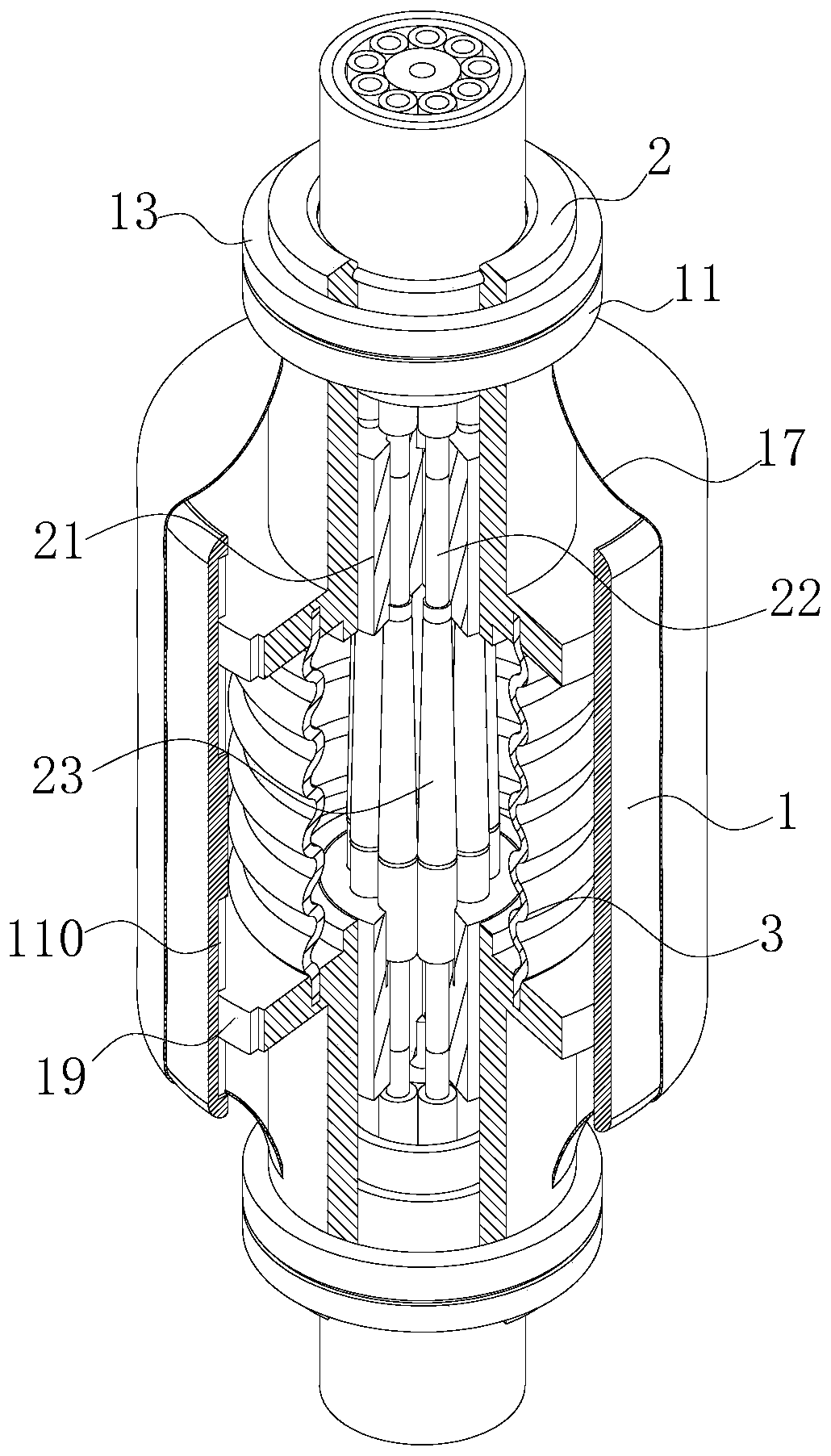
[0039] As an embodiment of the present invention, guide grooves (110) are opened on the inner arc surface of the fixed shell (1) at the positions of the two movable blocks (2); the outer arcs of the two movable blocks (2) The position facing the corresponding guide groove (110) is fixedly connected with the limit block (19), and the limit block (19) is all slidably connected in the corresponding guide groove (110); when working, due to the influence of the gravity of the optical fiber bundle itself , the optical fiber bundle is often subject to uneven tensile stress, so there will be serious unevenness in the pulling force of the optical fiber bundle on the movable block (2), so when the movable block (2) slides inside the fixed block (11), it is easy to appear Axis deflection problem, which in turn causes non-parallel phenomena on the opposite sides of the two movable blocks (2), which not only easily causes damage to the movable conduit (23), but also affects the normal condu...


PUM


Abstract

The invention belongs to the technical field of optical fiber production and use, and particularly relates to an optical fiber bundle. According to the optical fiber bundle, an optical fiber connectorused in the production process comprises a fixed shell, a movable block and a corrugated pipe; the fixed shell is of a cylinder structure; through holes penetrating up and down are formed in the endfaces of the two sides of the fixed shell; movable blocks are slidably connected to the interior of the through holes of the fixed shell at the positions close to the end faces of the two sides of thefixed shell, and the two movable blocks are both of a step-shaped structural design; and the side faces of the opposite sides of the two movable blocks are jointly and fixedly connected with the samecorrugated pipe. According to the invention, rapid and effective conduction of optical fiber bundles is effectively realized, and telescoping of the optical fiber connector is realized through an elastic structure, so that buffer protection is effectively performed on the joint of the two optical fiber bundles, the pulling force under special conditions is reduced, and the problem of connection failure is avoided.

Description

technical field [0001] The invention belongs to the technical field of optical fiber production and use, in particular to an optical fiber bundle. Background technique [0002] Optical fiber is short for optical fiber. It is a fiber made of glass or plastic that can be used as a light transmission tool. The transmission principle is 'total reflection of light'. [0003] Existing telecommunication cables have found increasing use in a wide variety of electronic and telecommunications applications. A telecommunication cable includes or surrounds one or more telecommunication optical fibers. The fiber optic cable provides structure and protection for the optical fibers within the cable. The connected fiber optic subunits of the bundle can be used to interconnect equipment within a network installation or data center. [0004] According to the production process of CN107783234B a kind of optical cable, in the prior art, when wiring and pulling wires, the problem of insufficient...

Claims


Application Information

Patent Timeline
IPC IPC(8): G02B6/38G02B6/44
CPCG02B6/3885G02B6/3875G02B6/4486G02B6/443G02B6/4436G02B6/44384
Inventor 蔡先民吴国良
Owner 安徽易知谷信息科技有限公司
Why Eureka
Try Eureka