High refresh rate waveform mapping method and digital oscilloscope

A mapping method and refresh rate technology, applied in the direction of digital variable display, digital variable/waveform display, instruments, etc., can solve the problems of inability to parallel processing of multiple columns of waveforms, reduction of waveform refresh rate, and reduction of refresh rate.

Active Publication Date: 2020-08-11
SHENZHEN CITY SIGLENT TECH
View PDF8 Cites 2 Cited by
  • Summary
  • Abstract
  • Description
  • Claims
  • Application Information

AI Technical Summary

Problems solved by technology

[0006] To sum up, regardless of the number N of points to be displayed in each column, the waveform mapping mechanism adopted in the prior art can only process the waveform column by column, so that when N is less than L, the waveform cannot be processed in parallel in multiple columns. The refresh rate is reduced; the waveform needs to be mapped codeword by codeword when performing column mapping, so that the processing time of each column is not only related to the number of points N displayed in each column (ceil(N / L)), but also related to the signal amplitude C max -C min There is a relationship, but as the signal amplitude becomes larger, the processing time of each frame will also increase, which will result in a decrease in the waveform refresh rate

Method used


Image

  • High refresh rate waveform mapping method and digital oscilloscope
  • High refresh rate waveform mapping method and digital oscilloscope
  • High refresh rate waveform mapping method and digital oscilloscope

Examples


Embodiment 1

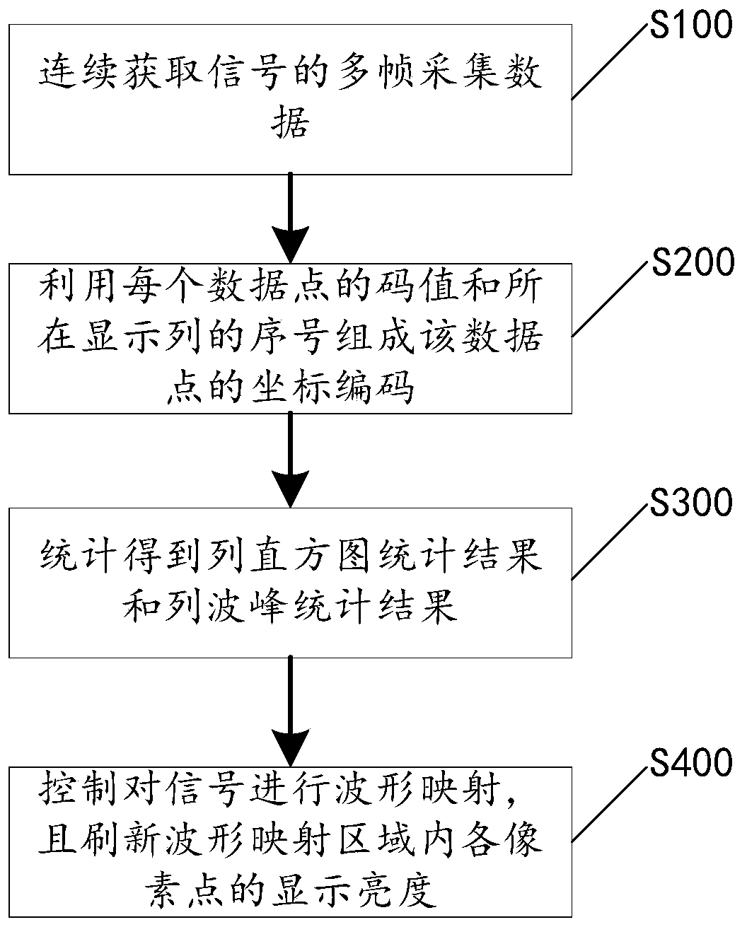
[0029] Please refer to figure 1 , the present application discloses a waveform mapping method with a high refresh rate. The waveform mapping method includes steps S100-S400, which will be described respectively below.

[0030] Step S100, continuously acquire multi-frame acquisition data of the signal, where each data point in the acquisition data is sequentially numbered according to the output order.

[0031] It should be noted that each data point in the collected data has a position number in the effective data stream, and the data point is output sequentially according to the position number. For example, in the effective data stream, the data number of the first clock is {L-1,L-2,..1,0}, the data sequence number of the second clock is {2L-1,2L-2,..L+1,L}, and the data sequence number of the third clock is {3L-1,3L-2,..2L+1,2L}, and so on, each data point can be marked. However, in this embodiment, each data point in each frame of collected data is sequentially numbered ...

Embodiment 2

[0057] Please refer to FIG. 6 , on the basis of the waveform mapping method disclosed in Embodiment 1, this application also discloses a digital oscilloscope 1 correspondingly, which includes a cache module 11 , an encoding module 12 , a statistics module 13 and a waveform display module 14 .

[0058] The buffer module 11 is used to continuously acquire multi-frame acquisition data of the signal, and buffer each frame of acquisition data, and each data point in each frame of acquisition data is sequentially numbered according to the output sequence. The buffer module 11 can be connected with a signal sampling component (such as an ADC conversion module) in the digital oscilloscope, and buffer the digitized data after sampling, interpolation or trigger position synchronization.

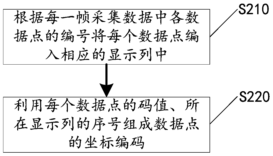
[0059] The coding module 12 is connected with the cache module 11, and is used to compile each data point into a corresponding display column according to the numbering of each data point in each frame ...


PUM


Abstract

The invention discloses a high refresh rate waveform mapping method and a digital oscilloscope. The method comprises the following steps: continuously obtaining multiple frames of collected data of signals (S100); arranging each data point of each frame of collected data in a corresponding display array, and forming a coordinate code of the data point by utilizing the code value of each data pointand the serial number of the display array where the data point stays (S200); counting the times that each data point appears at corresponding coordinate code to obtain the statistical result of thearray column diagram, and counts the maximal code value and minimal code value in each display array so as to obtain an array peak value statistical result (S300); according to the statistical result,carrying out waveform mapping on the signals, and refreshing the display brightness of each pixel in the waveform mapped region (S400). According to the waveform mapping method, a statistical value mapping mechanism is used to replace a conventional each frame individual mapping mechanism, the situation that data acquisition of each frame needs individual mapping is avoided, the time for waveformmapping is reduced, and the refresh rate is improved.

Description

technical field [0001] The invention relates to the technical field of digital signal processing, in particular to a waveform mapping method with a high refresh rate and a digital oscilloscope. Background technique [0002] When doing modern electronic design, engineers need to pay special attention to the instantaneous abnormal signals in electronic signals, such as jitter, short pulse, low-frequency interference and instantaneous errors, etc. It is often necessary to use an oscilloscope to capture such abnormal signals and analyze and display them . The waveform refresh rate is used to indicate the maximum number of times the oscilloscope can capture waveforms per second, and it is one of the important indicators for judging the performance of a digital oscilloscope. Generally, the higher the waveform refresh rate, the shorter the dead time of the oscilloscope, and the stronger the ability to capture abnormal signals. Therefore, designing a higher waveform refresh rate is...

Claims


Application Information

Patent Timeline
Patent Type & Authority Applications(China)
IPC IPC(8): G01R13/02
CPCG01R13/0209G01R13/029
Inventor 李振军郑文明吴乾科
Owner SHENZHEN CITY SIGLENT TECH
Why Eureka
Try Eureka