
Partial pressure watering device for greenhouse planting

The technology of a sprinkler device and a shed body is applied in the directions of fertilization device, liquid fertilizer distribution, and pressure spreading method of liquid fertilizer. The effect of irrigation and watering is even and thorough, and the overall design is reasonable

Pending Publication Date: 2020-08-14
YANCHENG WANYANG AGRICULTURAL PRODUCTS CO LTD
View PDF6 Cites 1 Cited by
  • Summary
  • Abstract
  • Description
  • Claims
  • Application Information

AI Technical Summary

Problems solved by technology

However, most of the existing sprinkling devices for greenhouse planting are fixed mode or manual sprinkling, the artificial sprinkling efficiency is low, and the fixed sprinkling method will lead to narrow sprinkling range, uneven sprinkling, and sometimes excessive water pressure will cause damage to plants

Method used


Image

  • Partial pressure watering device for greenhouse planting
  • Partial pressure watering device for greenhouse planting
  • Partial pressure watering device for greenhouse planting

Examples


Embodiment 1

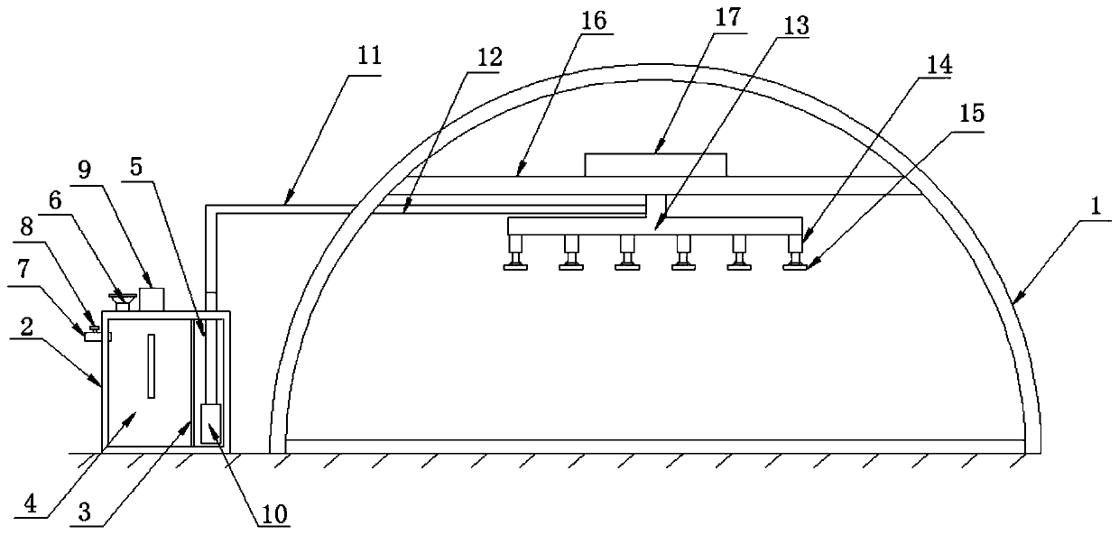
[0028] Such as Figure 1-3 As shown, a greenhouse planting partial pressure sprinkler device according to an embodiment of the present invention includes a shed body 1, a water storage tank 2 is provided on one side of the shed body 1, and the water storage tank 2 is a cavity structure. A vertical sieve plate 3 is provided in the cavity of the water storage tank 2, and a chamber one 4 and a chamber two 5 are respectively formed between the sieve plate 3 and the water storage tank 2, and the chamber one The top of 4 is provided with feeding port 6, and described feeding port 6 is connected with described chamber one 4, and the top side of described chamber one 4 is provided with water inlet pipe 7, and described water inlet pipe 7 is provided with valve 8. The first chamber 4 is provided with a stirring mechanism 9, and the bottom of the second chamber 5 is provided with a water pump 10, and the output end of the water pump 10 runs through the inner wall of the second chamber 5...

Embodiment 2

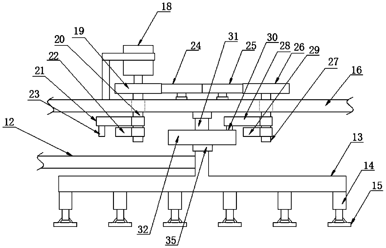
[0031] Such as figure 2 As shown, the tooth width, addendum circle diameter and modulus of the second gear 24 and the third gear 25 are the same.

[0032] Such as figure 2 As shown, the tooth width, addendum circle diameter and modulus of the first gear 19 and the fourth gear 26 are the same.

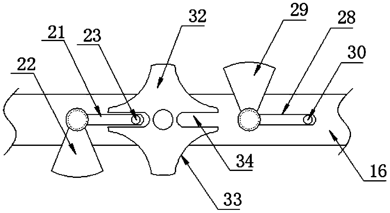
[0033] Such as figure 2 , image 3 As shown, the first arc block 22 and the second arc block 29 are adapted to the arc groove 33, and the first pin 23 and the second pin 30 are compatible with the limiting groove 34. adaptation.

[0034] Such as figure 1 As shown, the feeding port 6 is provided with a cover. Thereby avoid impurity to enter in the water storage tank 2. In practical applications, a sealing ring may be arranged in the above-mentioned cover.

[0035] Such as figure 2 As shown, the first rotary motor 18 is provided with a fixing frame, and the bottom end of the fixing frame is connected with the installation plate 16 . Thereby, the stability of the rotary elect...


PUM


Abstract

The invention discloses a partial pressure watering device for greenhouse planting. The device comprises a greenhouse body, wherein a water storage tank is arranged on one side of the greenhouse bodyand is of a cavity structure, a sieve plate in the vertical direction is arranged in the cavity of the water storage tank, a first cavity and a second cavity are formed between the sieve plate and thewater storage tank, a feeding opening is formed in the top end of the first cavity, the feeding opening communicates with the first cavity, a water inlet pipe is arranged on one side of the top of the first cavity, a valve is arranged on the water inlet pipe, a stirring mechanism is arranged in the first cavity in a penetrating mode, a water pump is arranged at the bottom of the cavity of the second cavity, the output end of the water pump penetrates through the inner wall of the second cavity to be connected to one end of a flow guide pipe, the other end of the flow guide pipe penetrates through the greenhouse body and is connected to one end of a hose, and the other end of the hose is connected to a water pipe. The partial pressure watering device has beneficial effects that the overalldesign is reasonable, the watering efficiency of greenhouse planting is improved, meanwhile, watering is more uniform and thorough, and watering irrigation of plants is facilitated.

Description

technical field [0001] The invention relates to the field of planting, in particular to a partial pressure watering device for greenhouse planting. Background technique [0002] Many existing fruits, vegetables, and flowers are planted in greenhouses. Greenhouse planting has many advantages, and it is not affected by the season or the weather, and it can have a good harvest at any time. In greenhouse cultivation, watering the planted plants is a huge project. In addition to ground irrigation, some plants also need frequent watering. grow. However, most of the existing sprinkling devices for greenhouse planting are fixed mode or manual sprinkling, the efficiency of manual sprinkling is low, and the fixed sprinkling mode will lead to narrow sprinkling range, uneven sprinkling, and sometimes excessive water pressure will cause damage to plants. [0003] Aiming at the problems in the related technologies, no effective solution has been proposed yet. Contents of the invention...

Claims


Application Information

Patent Timeline
Patent Type & Authority Applications(China)
IPC IPC(8): A01C23/04
CPCA01C23/047
Inventor 陈济刚
Owner YANCHENG WANYANG AGRICULTURAL PRODUCTS CO LTD
Learn More