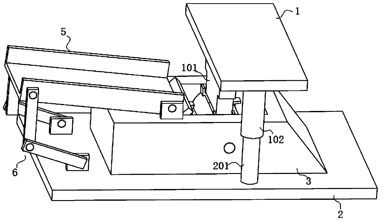
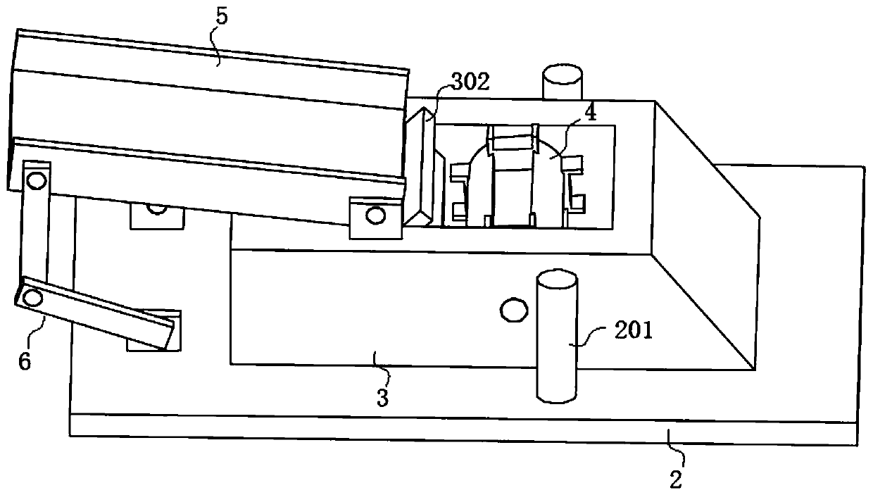
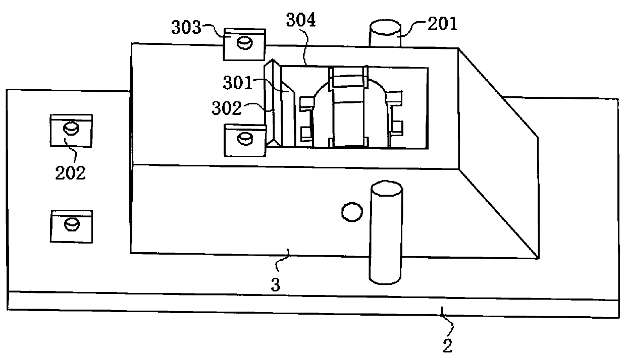
Hoop stamping die capable of achieving automatic discharging

A technology of automatic material discharge and stamping die, which is applied in the direction of manufacturing tools, ejection equipment, metal processing equipment, etc., and can solve the problems of low efficiency of manual feeding

Inactive Publication Date: 2020-08-14
HEFEI ZHENGTE MACHINERY CO LTD
View PDF0 Cites 3 Cited by
  • Summary
  • Abstract
  • Description
  • Claims
  • Application Information

AI Technical Summary

Problems solved by technology

[0003] The purpose of the present invention is to provide a hoop stamping die with automatic discharge that improves processing efficiency. A rectangular groove is provided on the boss, and a work cylin

Method used


Image

  • Hoop stamping die capable of achieving automatic discharging
  • Hoop stamping die capable of achieving automatic discharging
  • Hoop stamping die capable of achieving automatic discharging

Examples


Embodiment Construction

[0024] The following will clearly and completely describe the technical solutions in the embodiments of the present invention with reference to the accompanying drawings in the embodiments of the present invention. Obviously, the described embodiments are only some, not all, embodiments of the present invention. Based on the embodiments of the present invention, all other embodiments obtained by persons of ordinary skill in the art without creative efforts fall within the protection scope of the present invention.

[0025] In the description of the present invention, it should be understood that the terms "rectangular slot", "upper", "lower", "processed slot", "top", "middle", "length", "inner", "peripheral side ” and other indications of orientation or positional relationship are only for the convenience of describing the present invention and simplifying the description, rather than indicating or implying that the components or elements referred to must have a specific orient...


PUM


Abstract

The invention discloses a hoop stamping die capable of achieving automatic discharging, and relates to the technical field of hoop machining devices. The hoop stamping die comprises an upper die and alower die. A stamping head is fixedly connected to the upper die. A boss is arranged on the lower die. A rectangular groove is formed in the boss. A work barrel is connected in the rectangular groovein a rotating manner. Multiple machining grooves matched with the stamping head are formed in the circumferential face of the work barrel. The end, located on the rectangular groove, on the boss is connected with a feeding plate in a rotating manner. A discharge port is arranged on the portion, located below the work barrel, in the rectangular groove. According to the hoop stamping die, the rectangular groove is formed in the boss, the work barrel is connected in the rectangular groove in the rotating manner, meanwhile, the feed plate is connected to a work table in a rotating manner, and therefore automatic feeding and discharging of hoops are achieved, and the machining efficiency of the hoops is improved.

Description

technical field [0001] The invention belongs to the technical field of hoop processing equipment, in particular to a hoop stamping die for automatic discharge. Background technique [0002] The U-shaped hoop forming mold in the prior art requires workers to manually load and take parts, and the distance between the upper template and the lower template is small. When manually feeding materials, there are problems of low production efficiency and potential safety hazards. The viewing angle will be blocked by the stopper on the mold, so it often happens that the workers forget to take off the processed parts and continue to load the material, which will cause damage to the mold, and at the same time, the previous processed part will also be scrapped, and the subsequent loading It cannot be formed, the processing efficiency is low, and raw materials are wasted. Contents of the invention [0003] The purpose of the present invention is to provide a hoop stamping die with auto...

Claims


Application Information

Patent Timeline
IPC IPC(8): B21D22/02B21D43/16B21D45/02
CPCB21D22/02B21D43/16B21D45/02
Inventor 孙健
Owner HEFEI ZHENGTE MACHINERY CO LTD
Why Eureka
Try Eureka