Working method of intelligent stamping device

A technology of stamping device and working method, applied in the field of stamping device, to achieve the effect of ensuring stamping efficiency, ensuring stamping effect, and small stamping force

Active Publication Date: 2020-08-14
湛江市顺泽实业有限公司
View PDF10 Cites 4 Cited by
  • Summary
  • Abstract
  • Description
  • Claims
  • Application Information

AI Technical Summary

Problems solved by technology

[0002] For example, the public number CN204451241U name is an intelligent stamping device, including a base, a workbench, a guide post, a stamping head and a control circuit, the workbench is arranged above the base, and the guide post is also provided above the base, The stamping head is set on the guide post and can be driven by a driving mechanism to move up and down along the guide post. A position sensor and an acceleration sensor are arranged above the stamping head. The driving mechanism, the position sensor and the The acceleration sensor is connected with the control circuit; the disadvantage of this utility model is that it cannot be self-adjusted according to the thickness of stamping different plates

Method used


Image

  • Working method of intelligent stamping device
  • Working method of intelligent stamping device
  • Working method of intelligent stamping device

Examples


specific Embodiment approach 1

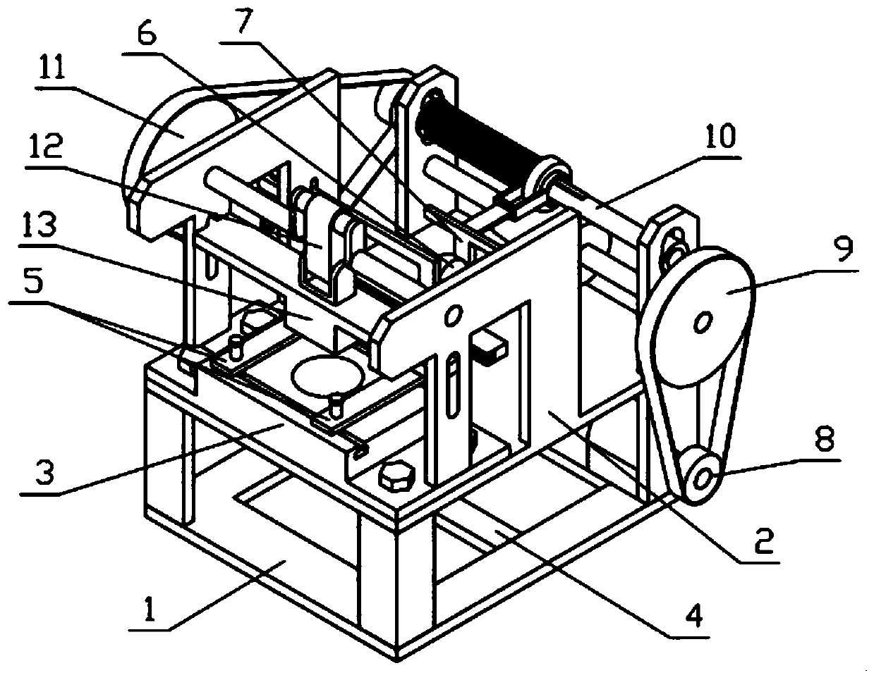
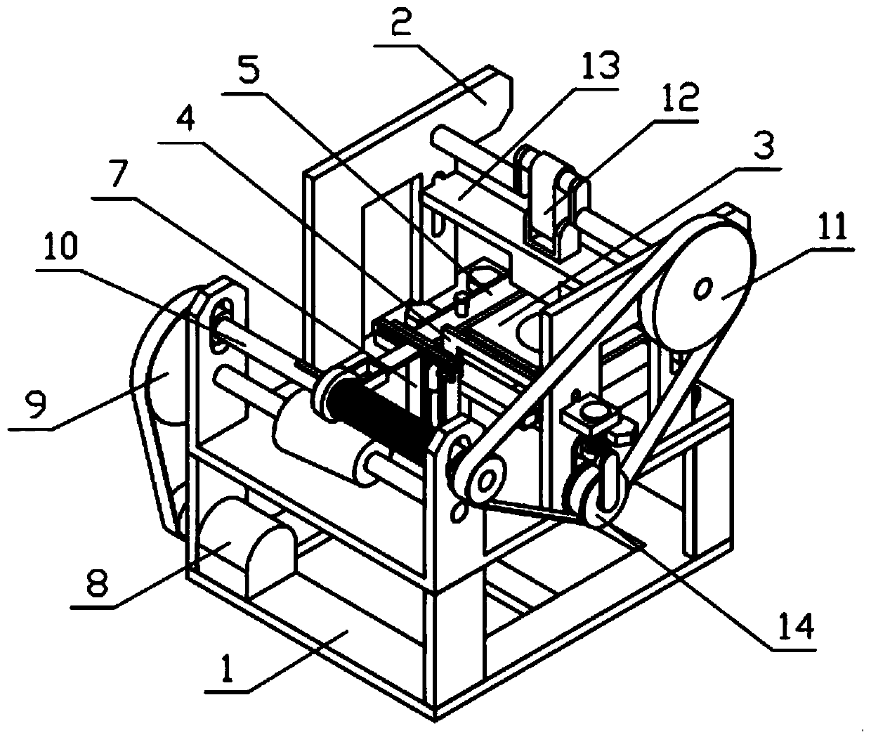
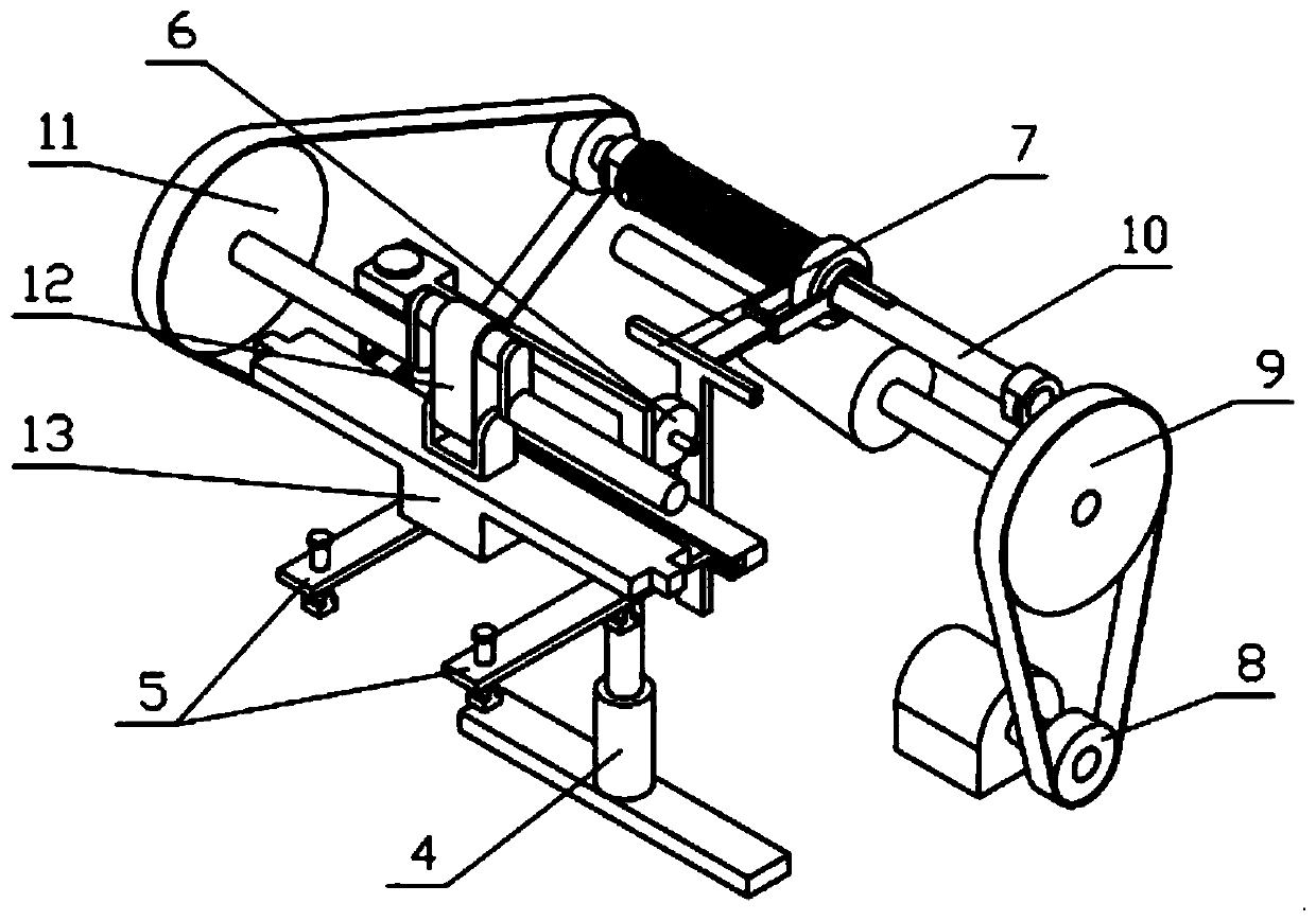
[0043] Combine below Figure 1-16 Describe this embodiment, an intelligent stamping device, including a chassis 1, a support bracket 2, a stamping platform 3, a pressing mechanism 4, a clamping mechanism 5, a lifting gear 6, a lifting rack 7, a power mechanism 8, and a transmission mechanism I9 , transmission mechanism II 10, stamping crank 11, stamping connecting rod 12, stamping die 13 and tensioning mechanism 14, the support bracket 2 is fixedly connected to the chassis 1, the stamping platform 3 is fixedly connected to the support bracket 2, and the compression mechanism 4. It is fixedly connected to the base frame 1. There are two clamping mechanisms 5. One end of the two clamping mechanisms 5 is both slidably connected to the stamping platform 3, and the other ends of the two clamping mechanisms 5 are both slidably connected to the pressing platform 3. On the mechanism 4, the lifting gear 6 is rotatably connected to the support bracket 2, one side of the lifting gear 6 i...

specific Embodiment approach 2

[0053] Combine below Figure 1-16 Describe this embodiment, this embodiment will further explain the eighth embodiment, the stamping crank 11 includes a crankshaft 11-1 and a stamping pulley 11-2, and the two ends of the crankshaft 11-1 are respectively rotatably connected to two supporting plates II2 -4, the crankshaft 11-1 is fixedly connected with a stamping pulley 11-2, the stamping pulley 11-2 and the drive pulley II 10-5 are connected through a belt drive, and one end of the stamping connecting rod 12 is hinged to the crankshaft 11-1 Eccentric position, the other end of the stamping connecting rod 12 is hinged on the stamping die 13, the stamping die 13 is located on the upper side of the stamping platform 3, and the two ends of the stamping die 13 are respectively slidingly connected in two vertical waist holes II2-5; the transmission belt Wheel II 10-5 drives the stamping pulley 11-2 to rotate around its own axis, the stamping pulley 11-2 drives the crankshaft 11-1 to ...

specific Embodiment approach 3

[0055] Combine below Figure 1-16 Describe this embodiment, this embodiment will further explain Embodiment 9, the tensioning mechanism 14 includes a tensioning bracket 14-1, a tensioning sliding column 14-2 and a tensioning pulley 14-3, and the tensioning bracket 14 -1 is fixedly connected with a tensioning sliding column 14-2, and the tensioning sliding column 14-2 is slidably connected to the tensioning support plate 4-5, and the tensioning sliding column 14-2 is covered with a compression spring II, and the compression spring II Located between the tension support 14-1 and the tension support plate 4-5, the lower end of the tension support 14-1 is rotatably connected with a tension pulley 14-3, the lower end of the tension pulley 14-3 and the stamping pulley 11-2 is in contact with the transmission belt between the transmission pulley II 10-5; when the transmission ratio between the transmission mechanism I9 and the transmission mechanism II10 changes, the relative distanc...


PUM


Abstract

The invention relates to stamping devices, in particular to a working method of an intelligent stamping device. The intelligent stamping device comprises an underframe, a supporting frame, a stampingplatform, a hold-down mechanism, two clamping mechanisms, a lifting gear, a lifting rack, a power mechanism, a transmission mechanism I, a transmission mechanism II, a stamping crank, a stamping connecting rod, a stamping die and a tensioning mechanism. According to the intelligent stamping device, the two clamping mechanisms can be simultaneously driven by the hold-down mechanism to clamp plateswith different thicknesses and lengths; the transmission ratio of the transmission mechanism I to the transmission mechanism II is adjusted while the hold-down mechanism drives the two clamping mechanisms to move to clamp a plate, so that the transmission ratio of the transmission mechanism I to the transmission mechanism II adapts to the change of the plate thickness; the device generates a highstamping force when the plate is thick so as to guarantee the stamping effect; and the device generates a low stamping force when the plate is thin so as to guarantee the stamping efficiency.

Description

technical field [0001] The invention relates to a stamping device, more specifically a working method of an intelligent stamping device. Background technique [0002] For example, the public number CN204451241U name is an intelligent stamping device, including a base, a workbench, a guide post, a stamping head and a control circuit, the workbench is arranged above the base, and the guide post is also provided above the base, The stamping head is set on the guide post and can be driven by a driving mechanism to move up and down along the guide post. A position sensor and an acceleration sensor are arranged above the stamping head. The driving mechanism, the position sensor and the The acceleration sensor is connected with the control circuit; the shortcoming of this utility model is that it cannot be self-adjusted according to the thickness of stamping different plates. Contents of the invention [0003] The purpose of the present invention is to provide a working method o...

Claims


Application Information

Patent Timeline
Patent Type & Authority Applications(China)
IPC IPC(8): B21D43/00B21D22/02B30B15/14
CPCB21D43/003B21D22/02B30B15/14
Inventor 王晓媛
Owner 湛江市顺泽实业有限公司
Why Eureka
Try Eureka