Clamping mechanism

A technology of clamping mechanism and clamping arm, which is applied in the direction of collets, manipulators, manufacturing tools, etc., and can solve the problem of high cost of clamping mechanism

Active Publication Date: 2020-08-14
ZHUHAI GREE INTELLIGENT EQUIP CO LTD +1
View PDF7 Cites 1 Cited by
  • Summary
  • Abstract
  • Description
  • Claims
  • Application Information

AI Technical Summary

Problems solved by technology

[0004] The main purpose of the present invention is to provide a clamping mechanism to solve the problem of high cost of the clamping mechanism in the prior art

Method used


Image

  • Clamping mechanism
  • Clamping mechanism
  • Clamping mechanism

Examples


Embodiment Construction

[0022] It should be noted that, in the case of no conflict, the embodiments in the present application and the features in the embodiments can be combined with each other. The present invention will be described in detail below with reference to the accompanying drawings and examples.

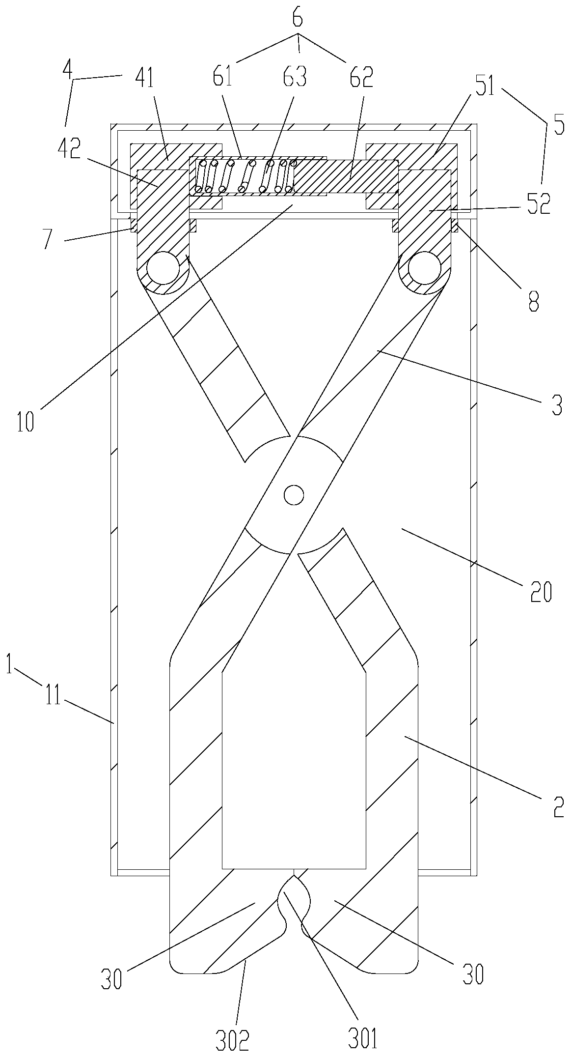
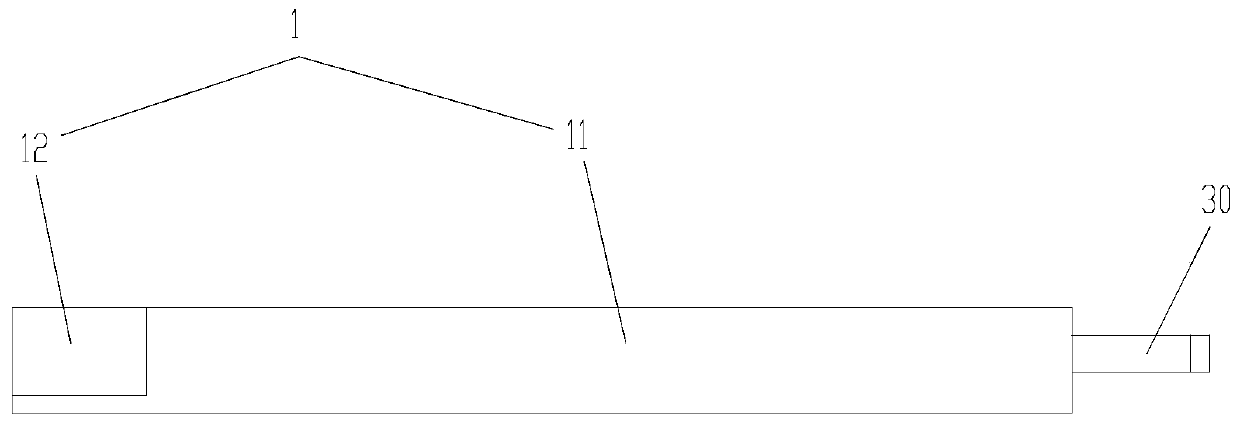
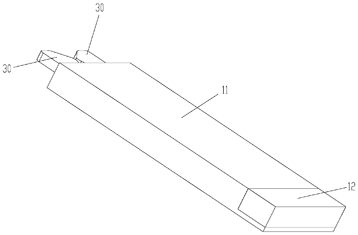
[0023] Please refer to Figure 1 to Figure 3 , the present invention provides a clamping mechanism, including: a support part 1; a first clamping arm 2, the first clamping arm 2 is rotatably installed on the support part 1; a second clamping arm 3, the second clamping arm The holding arm 3 is rotatably mounted on the supporting part 1; the first sliding assembly 4 is slidably arranged on the supporting part 1 along the first direction, and the first clamping arm 2 and the first sliding assembly 4 Hinged, the first sliding assembly 4 is set swayably along the second direction relative to the supporting part 1; the second sliding assembly 5, the second sliding assembly 5 is slidably arranged on ...


PUM


Abstract

The invention provides a clamping mechanism. The clamping mechanism comprises a supporting part, a first clamping arm, a second clamping arm, a first sliding assembly, a second sliding assembly and anelastic assembly, wherein the first clamping arm and the second clamping arm are rotatably installed on the supporting part; the first sliding assembly is slidably arranged on the supporting part inthe first direction, the first clamping arm is hinged to the first sliding assembly, and the first sliding assembly is arranged in the second direction in a shaking mode relative to the supporting part; the second sliding assembly is slidably arranged on the supporting part in the first direction, the second clamping arm is hinged to the second sliding assembly, and the second sliding assembly isarranged in the second direction in a shaking mode relative to the supporting part; and the elastic assembly is arranged in the first direction in a telescopic mode, one end of the elastic assembly isconnected with the first sliding assembly, and the other end of the elastic assembly is connected with the second sliding assembly, wherein the first direction is perpendicular to the second direction. According to the clamping mechanism, the problem of high cost of a clamping mechanism in the prior art is solved.

Description

technical field [0001] The invention relates to the field of clamps, in particular to a clamping mechanism. Background technique [0002] Clamping mechanisms are widely used in production operations. For example, when transferring, assembling, and processing workpieces, it is often necessary to use clamping mechanisms to clamp the workpieces. [0003] Existing clamping mechanisms generally use cylinders or complex mechanical drive structures to drive the grippers, thereby realizing the grasping of workpieces. The structure of these clamping mechanisms is complex and expensive, which limits the use of clamping mechanisms in some production occasional application. Contents of the invention [0004] The main purpose of the present invention is to provide a clamping mechanism to solve the problem of high cost of the clamping mechanism in the prior art. [0005] In order to achieve the above object, the present invention provides a clamping mechanism, comprising: a support pa...

Claims


Application Information

Patent Timeline
Patent Type & Authority Applications(China)
IPC IPC(8): B25J15/08
CPCB25J15/08
Inventor 张艳吉林祥龙胡为纬曾锦桢李玉娟邓鑫蓝秋红王健李佳辉章誉骞杨作硕
Owner ZHUHAI GREE INTELLIGENT EQUIP CO LTD
Why Eureka
Try Eureka