Retaining wall for water conservancy project

A technology for water conservancy projects and retaining walls, applied in water conservancy projects, marine engineering, coastline protection, etc., can solve the problems that retaining walls cannot meet the requirements of users, low construction efficiency, long construction period, etc. Potential safety hazards, improved efficiency, and the effect of high robustness

Inactive Publication Date: 2020-08-14
李凤玲 +4
View PDF8 Cites 0 Cited by
  • Summary
  • Abstract
  • Description
  • Claims
  • Application Information

AI Technical Summary

Problems solved by technology

[0003] The traditional retaining wall will be poured on site. The method of on-site construction will lead to a relatively long construction period and low construction efficiency. The traditional retaining wall can no longer meet the requirements of users.

Method used


Image

  • Retaining wall for water conservancy project
  • Retaining wall for water conservancy project
  • Retaining wall for water conservancy project

Examples


Embodiment Construction

[0026] A water conservancy engineering retaining wall of the present invention will be further described in detail below in conjunction with the accompanying drawings.

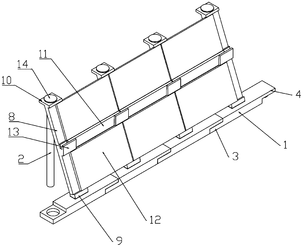
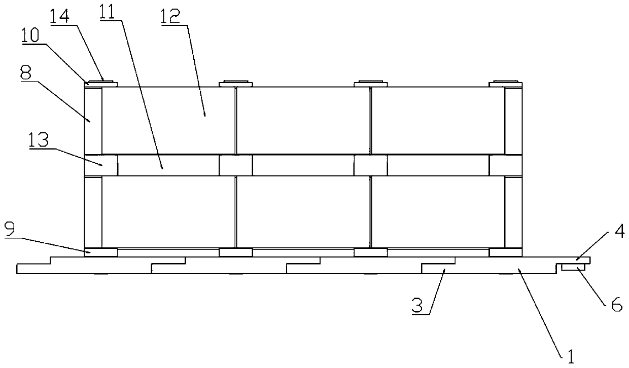
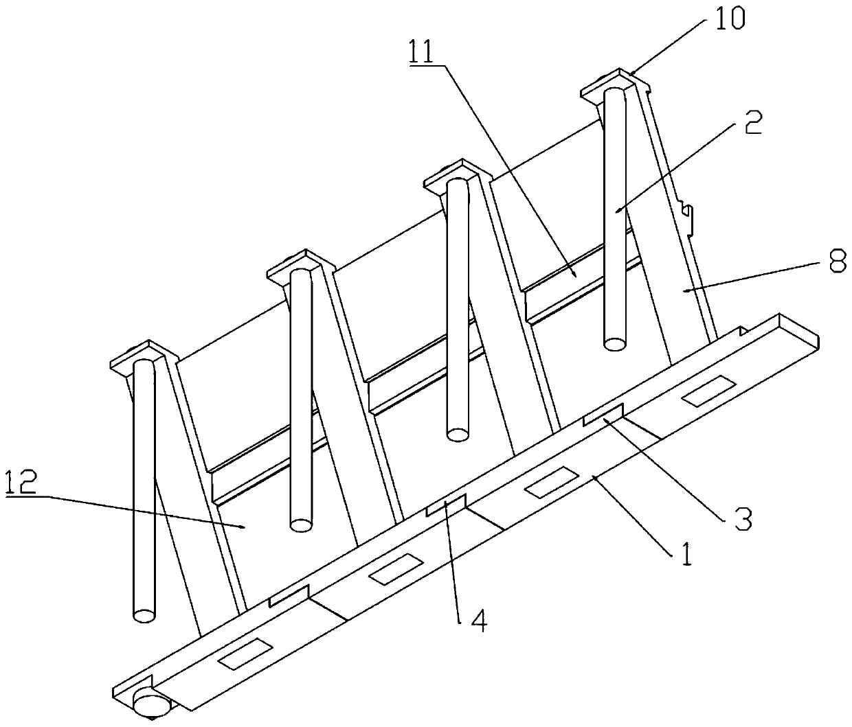
[0027] combined with Figure 1-8 , a water conservancy engineering retaining wall, comprising a bottom connection plate 1, a connection plate body and a column body 2;

[0028] Both ends of the bottom connecting plate 1 are respectively provided with a first connecting block 3 and a second connecting block 4, the lower side of the first connecting block 3 is parallel to the lower side of the bottom connecting plate 1, and the first connecting block The thickness of 3 is half of the thickness of the bottom connecting plate 1, the upper side of the second connecting block 4 is parallel to the upper side of the bottom connecting plate 1, and the thickness of the second connecting block 4 is half of the thickness of the bottom connecting plate 1, The length, width and thickness of the first connecting block 3 are...


PUM


Abstract

The invention relates to the technical field of water conservancy projects, in particular to a retaining wall for water conservancy project. The retaining wall comprises a bottom connecting plate, a connecting plate body and a column body, wherein a first connecting block and a second connecting block are arranged at the two ends of the bottom connecting plate respectively, a circular through holeis formed in the first connecting block, a cylindrical protrusion is arranged on the lower side of the second connecting block, a square hole is formed in the middle of the bottom connecting plate, the connecting plate body is composed of a supporting plate, a square block fixedly arranged on the lower portion of the supporting plate and an upper square plate fixed to the upper portion of the supporting plate, a round through hole is formed in the upper square plate, the column body penetrates through the round through hole, and a T-shaped connecting block and a soil retaining plate are arranged on the supporting plate, so that large excavation during construction is avoided, potential safety hazards are reduced, construction is rapid, and the working efficiency is improved; and through cooperation of the bottom connecting plate, the connecting plate body and the column body, sliding is not likely to occur, and high firmness is achieved.

Description

technical field [0001] The invention relates to the technical field of water conservancy engineering, in particular to a retaining wall of a water conservancy project. Background technique [0002] The retaining wall refers to the structure that supports the subgrade filling or hillside soil and prevents the deformation and instability of the filling or soil. In the cross section of the retaining wall, the part that is in direct contact with the supported soil is called the wall back; The part opposite to the back of the wall and facing the sky is called the wall surface; the part directly in contact with the foundation is called the base; the top surface of the wall opposite to the base is called the top of the wall; the front end of the base is called the toe of the wall; called the wall heel. [0003] The traditional retaining wall will be poured on site. The method of on-site construction will lead to a relatively long construction period and low construction efficiency...

Claims


Application Information

Patent Timeline
IPC IPC(8): E02B3/06E02B3/14
CPCE02B3/066E02B3/14
Inventor 李凤玲刘敏张万军董艳沙丙翠
Owner 李凤玲
Why Eureka
Try Eureka