Elevated ground

A ground and end face technology, applied in the field of architectural decoration, can solve problems such as large influence of levelness, difficulty in controlling levelness, and easy deformation, etc., and achieve the effects of lifting control, easy adjustment, and enhanced support strength

Inactive Publication Date: 2020-08-14
北京太伟宜居装饰工程有限公司 +1
View PDF6 Cites 1 Cited by
  • Summary
  • Abstract
  • Description
  • Claims
  • Application Information

AI Technical Summary

Problems solved by technology

[0004] It can be seen from the aforementioned prior art that the pavement of the ground in the living room, especially the paving of the ground in the living room that adopts the heating method of floor heating, mainly has the following problems: The levelness has a great influence, and a leveling layer needs to be set in advance for leveling; the levelness of each layered structure of the paved floor is difficult to control during the composite process, which has an impact on each other's levelness; sound insulation, heat preservation, heat storage, etc. The material strength of the functional floor is low, and it is easy to deform at the place where the floor load is concentrated

Method used


Image

  • Elevated ground
  • Elevated ground
  • Elevated ground

Examples


Embodiment 1

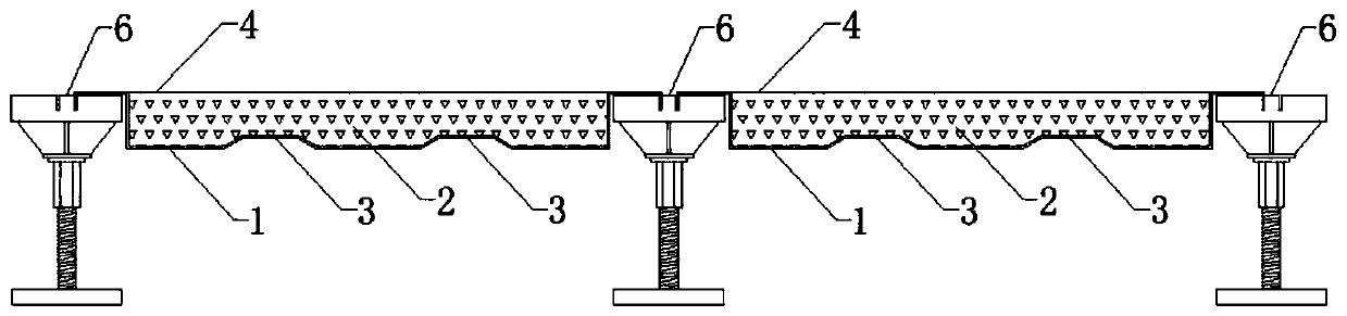
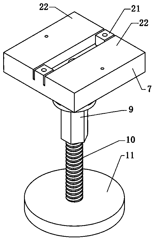
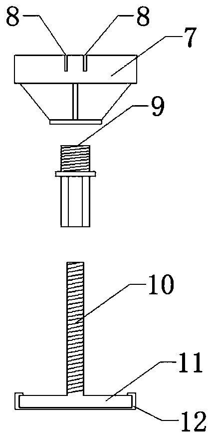
[0034] refer to Figure 1 to Figure 4 , Figure 8 to Figure 11 As shown, a raised ground includes a foot assembly 6 and an overhead board 1 connected with the foot assembly 6. The improvement is that the foot assembly 6 includes a support foot 11, a screw 10 connected with the support foot 11, and a screw 10 connected connection kit 9, the bracket 7 connected with the connection kit 9, the upper end of the connection kit 9 ​​is provided with a threaded connection portion, the bracket 7 is provided with a connecting hole 13 passing through the bracket 7, and the connection hole 13. At least the lower part is provided with an internal thread for connecting with the threaded connection part. The connecting sleeve 9 is provided with a through hole passing through the connecting sleeve 9. At least the lower part of the through hole is provided with an internal thread for connecting with the screw rod 10. The upper end of the screw 10 is provided with a screwing part 20; the length...

Embodiment 2

[0048] On the basis of embodiment 1, with reference to Figure 2 to Figure 4 As shown, the connecting portion is two slots 8 located on the upper part of the bracket 7 and symmetrically arranged on both sides of the connecting hole 13. The outer sides of the two slots 8 are the abutting surfaces 22, The middle is a non-contact surface 21 , the contact surface 22 is not higher than the non-contact surface 21 , and the bent portion of the erection rail is inserted into the slot 8 .

[0049] Further, the width of the card slot 8 matches the thickness of the erection track, and the distance between the card slot 8 and the edge of the bracket 7 matches the width of the erection track, so that the erection track can be firmly overlapped with the foot assembly 6 and place it in the slot 8.

[0050] Further, the abutting surface 22 is provided with a deep punching hole 14 . Self-tapping screws are used to pass through the erection rail and the deep punching hole 14, so that the over...

Embodiment 3

[0053] On the basis of embodiment 1, with reference to Figure 5 , 6 As shown, the connecting portion is a card slot 8 located on the upper part of the bracket 7 and on one side of the connecting hole 13, one side of the card slot 8 is the abutment surface 22 abutting against the erection track, and the other side is the non-contact surface 22. The abutment surface 21, the abutment surface 22 is not higher than the non-abutment surface 21, a through hole is opened on the position corresponding to the connection hole 13 on the erection track, and the bending part of the erection track is snapped into card slot 8.

[0054] The eccentric clamping method of this embodiment is mainly used for floor laying near the foot of the side facade. Due to the eccentric arrangement, it can avoid the subsidence and deformation of the aerial plate 1 caused by the inclination of the support foot assembly 6 in the symmetrical arrangement. The tool can be passed through the through hole, and the...


PUM


Abstract

The invention relates to an elevated ground comprising supporting foot assemblies and elevated plates connected with the supporting foot assemblies. Each supporting foot assembly comprises a supporting foot, a threaded rod connected with the supporting foot, a connection kit connected with the threaded rod and a supporting block connected with the connection kit. A threaded connection part is arranged at the upper end of each connection kit. Each supporting block is provided with a connection hole penetrating through the supporting block. Internal threads connected with the corresponding threaded connection part are arranged on at least the lower portion of each connection hole. Each connection kit is provided with a through hole penetrating through the connection kit. Internal threads connected with the corresponding threaded rod are arranged on at least the lower portion of each through hole. A twisting part is arranged on the upper end portion of each threaded rod. Elevated rails are arranged at the two ends of each elevated plate. A connection part connected with the corresponding elevated rail is arranged on the upper portion of each supporting block. The elevated ground has the advantages of being simple in structure, convenient and rapid to construct and adjustable in levelness, the labor cost can be saved, and the construction period can be shortened.

Description

technical field [0001] The invention relates to the field of architectural decoration, in particular to a raised ground. Background technique [0002] Prefabricated decoration means that the parts and components required for decoration are prefabricated, and then assembled on site, so as to reduce the measurement, cutting and other processes during on-site construction operations. Compared with traditional decoration and decoration work, the construction work of prefabricated decoration and decoration is simpler and more convenient, which can improve work efficiency and reduce material waste, and keep the work site as tidy as possible. It is a more green and environmentally friendly decoration and decoration method . [0003] The pavement of the ground in the living room of existing buildings is usually to install a leveling layer and a support layer on the concrete floor slab before installing the floor surface layer, and sometimes it is necessary to add a sound insulation...

Claims


Application Information

Patent Timeline
Patent Type & Authority Applications(China)
IPC IPC(8): E04F15/024E04F15/18E04F15/20
CPCE04F15/02447E04F15/02452E04F15/02458E04F15/02476E04F15/18E04F15/203E04F2290/04E04F2290/043
Inventor 武建振安德亮魏泽雨笱欢熊奘江海兵郭成文李金辉贾鹏飞余天江钱泽军李宏伟彭明琦
Owner 北京太伟宜居装饰工程有限公司
Why Eureka
Try Eureka