Electromagnetic auxiliary leather bag type constant-pressure energy accumulator

A technology of constant pressure accumulator and skin bag, applied in the direction of accumulator device, actuator accumulator, fluid pressure actuating device, etc. The effect of improving energy recovery efficiency, improving equipment safety and prolonging service life

Active Publication Date: 2020-08-14
TAIYUAN UNIVERSITY OF SCIENCE AND TECHNOLOGY
View PDF11 Cites 2 Cited by
  • Summary
  • Abstract
  • Description
  • Claims
  • Application Information

AI Technical Summary

Problems solved by technology

[0004] However, the traditional air-filled accumulator is difficult to fill the oil due to the increase of the pressure in the oil chamber in the later stage of hydraulic oil filling, resulting in the inability to store part of the energy in the accumulator; lower, less power
In particular, when the oil discharge pressure of the accumulator is lower than the system pressure, the accumulator cannot continue to output pressure oil, resulting in a low overall energy storage density and affecting the overall performance of the hydraulic system

Method used


Image

  • Electromagnetic auxiliary leather bag type constant-pressure energy accumulator
  • Electromagnetic auxiliary leather bag type constant-pressure energy accumulator
  • Electromagnetic auxiliary leather bag type constant-pressure energy accumulator

Examples


Embodiment Construction

[0030] The present invention will be further described below in conjunction with the embodiments and the accompanying drawings.

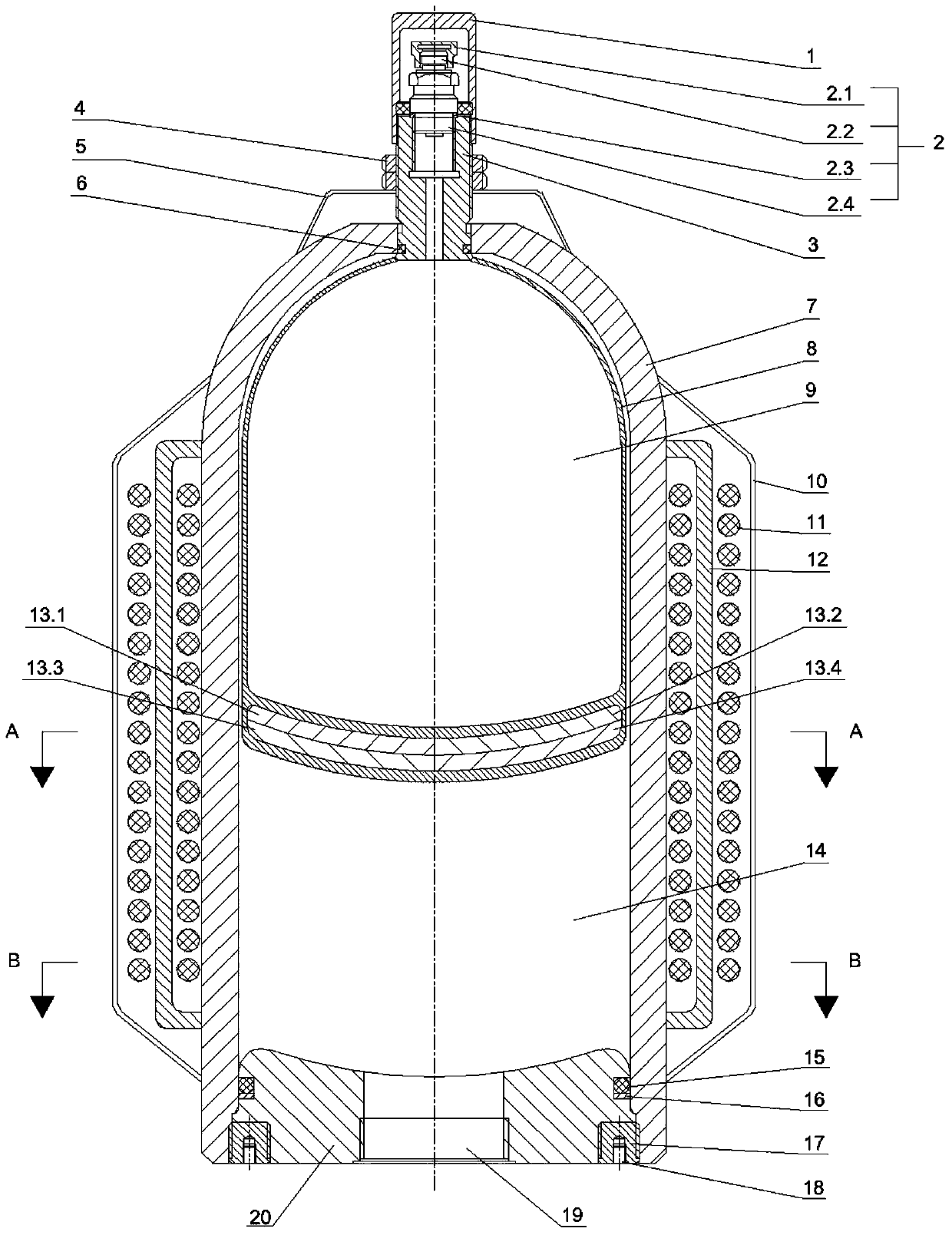
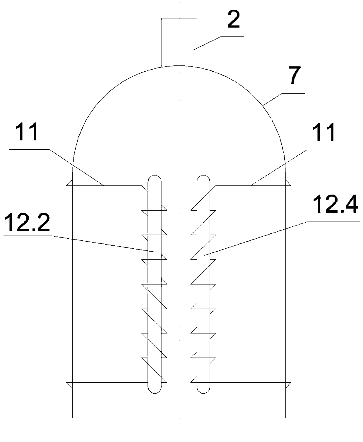
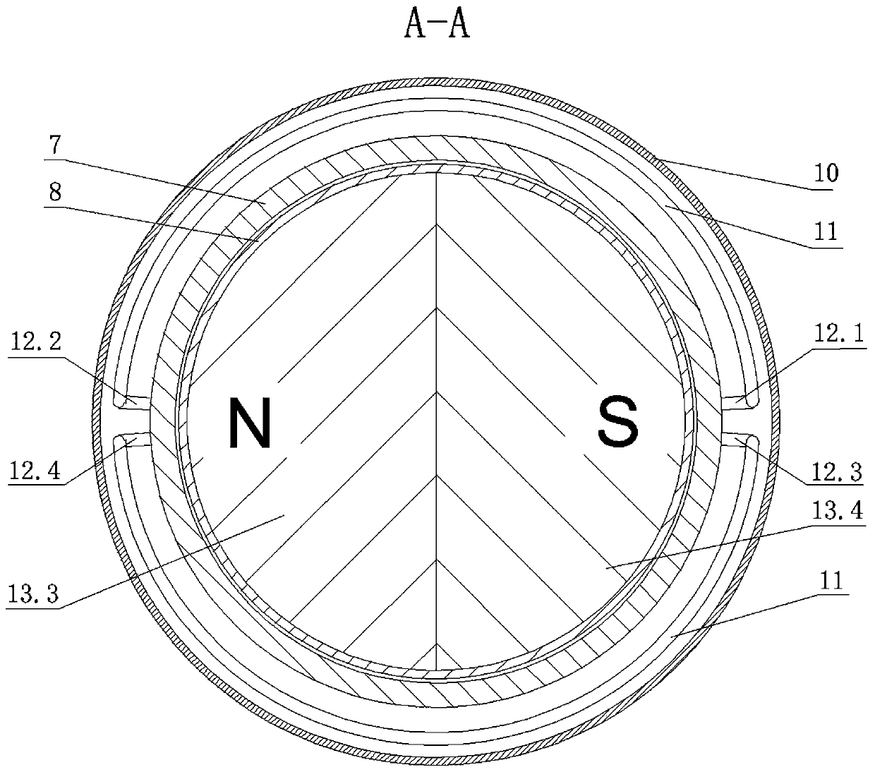
[0031] like figure 1 and figure 2 As shown, an electromagnetic auxiliary bladder type constant pressure accumulator described in this embodiment includes a housing 7, an elastomer bladder 8 disposed in the housing 7, an end cover 20 disposed at the bottom of the housing 7 and The air valve seat 3 that is located at the top of the housing 7; There is sealing ring 6, which can play a sealing role.

[0032] The elastomer bladder 8 divides the housing 7 into an air chamber 9 and a liquid chamber 14, and the air valve seat 3 is provided with an inflation valve 2 communicating with the air chamber 9, and the inflation valve 2 is connected to the air valve valve The seat 3 is threaded, and the elastomer bladder 8 is filled with gas through the inflation valve 2 .

[0033] The inflation valve 2 includes four parts: an air valve sealing cap 2.1, an air ...


PUM


Abstract

The invention relates to an electromagnetic auxiliary leather bag type constant-pressure energy accumulator. The electromagnetic auxiliary leather bag type constant-pressure energy accumulator aims tosolve the technical problem that it is difficult for a traditional air bag type energy accumulator to charge oil in the later period of hydraulic oil charging, part of energy cannot be stored, poweris weakened in the later period of oil drainage, and the overall working performance of a hydraulic system is influenced. The energy accumulator comprises a shell body, an elastic body leather bag arranged in the shell body, an end cover arranged at the bottom of the shell body and an air valve seat arranged at the top of the shell body; and the energy accumulator further comprises a permanent magnet module, four coil winding columns, two wires and a numerical control power supply connected with the wires, wherein the permanent magnet module is arranged in the bottom of the elastic body leather bag, the four coil winding columns are arranged on the outer wall of the shell body, and the two ends of each wire are wound around the two coil winding columns located on the different sides in ananticlockwise mode and a clockwise mode correspondingly. According to the energy accumulator, the stability of oil pressure output in the working process can be guaranteed, the oil charging and drainage efficiency and the energy recovery efficiency of the energy accumulator are improved, and the working performance of the hydraulic system is improved.

Description

technical field [0001] The invention belongs to the field of hydraulic transmission control technology and energy storage technology, and in particular relates to an electromagnetic auxiliary bladder type constant pressure accumulator. Background technique [0002] An accumulator is an energy storage device that can store oil with a certain pressure energy in a pressure-resistant container and release it when needed. As an important accessory in the hydraulic system, the accumulator plays a vital role in ensuring the normal operation of the hydraulic system, improving its dynamic quality, maintaining working stability, prolonging the working life of the equipment, auxiliary energy, and reducing noise. [0003] Accumulators can be divided into spring type, gravity type and gas-filled type according to the loading method. Spring type and gravity type are rarely used because of their own limitations, and gas-filled accumulators are more widely used at present. Air-filled accu...

Claims


Application Information

Patent Timeline
Patent Type & Authority Applications(China)
IPC IPC(8): F15B1/16F15B1/033F15B1/08F15B1/22
CPCF15B1/033F15B1/08F15B1/165F15B1/22F15B2201/205F15B2201/3152F15B2201/4056F15B2201/51
Inventor 马浩钦高有山鲍东杰左旸秦泽王恺
Owner TAIYUAN UNIVERSITY OF SCIENCE AND TECHNOLOGY
Why Eureka
Try Eureka