Measuring device for municipal engineering

A measurement device and engineering technology, applied in the direction of measurement device, radio wave measurement system, use of re-radiation, etc., can solve the problems of inconvenient movement, cost a lot of time, inconvenient operation, etc., and achieve the effect of convenient movement, simple structure and convenient operation.

Inactive Publication Date: 2020-08-14
杨明清
View PDF8 Cites 9 Cited by
  • Summary
  • Abstract
  • Description
  • Claims
  • Application Information

AI Technical Summary

Problems solved by technology

[0004] The purpose of the present invention is to solve the problem that the existing measuring device first needs to spend a lot of time to adjust the levelness of the measuring device when measuring, and secondly, it is not easy to move. Every time it moves, it needs to be put away and transported, and it needs to be unfolded again to adjust the level when it is used. Position, operation is very inconvenient shortcomings, and proposed a measuring device for municipal engineering

Method used


Image

  • Measuring device for municipal engineering
  • Measuring device for municipal engineering
  • Measuring device for municipal engineering

Examples


Embodiment 1

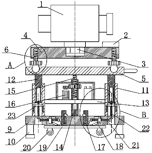
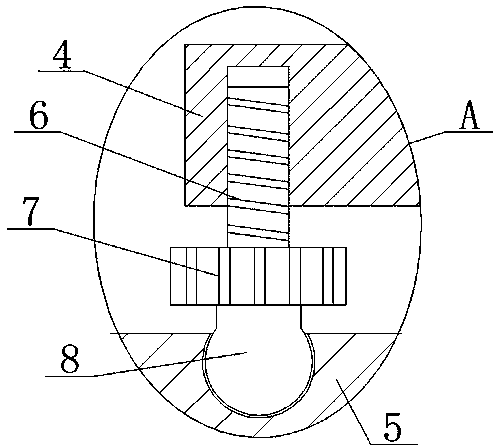
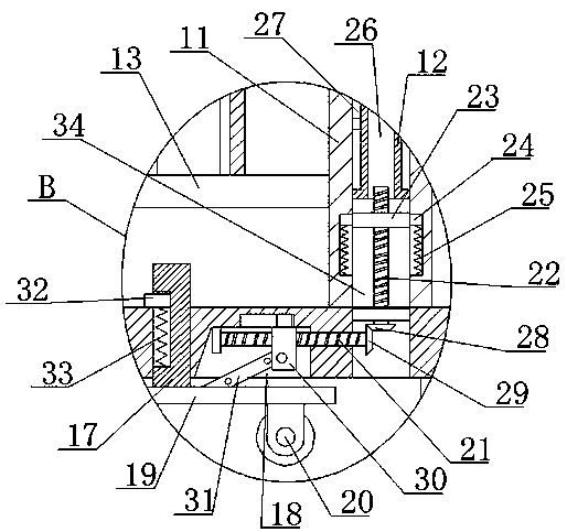
[0030] refer to Figure 1-5 , a measuring device for municipal engineering, comprising a laser range finder 1, a level 2 and a support plate 4, the laser range finder 1 and the level 2 are all arranged on the top of the support plate 4, and the laser range finder 1 is provided with a display, which can The distance is displayed for easy observation. A placement plate 5 is arranged under the support plate 4, and a horizontal adjustment structure is arranged between the support plate 4 and the placement plate 5. Four square rods 12 are fixedly installed on the bottom of the placement plate 5, and four The outer sides of the square rods 12 are all slidably equipped with rectangular columns 11, the bottoms of the four rectangular columns 11 are all fixedly installed with the same base 9, and the same connecting plate 13 is fixedly installed on the four rectangular columns 11, and the connecting plate 13 is provided with Lifting mechanism, the lifting mechanism is compatible with t...

Embodiment 2

[0041] refer to Figure 1-5 , a measuring device for municipal engineering, comprising a laser range finder 1, a level 2 and a support plate 4, the laser range finder 1 and the level 2 are all arranged on the top of the support plate 4, and the laser range finder 1 is provided with a display, which can The distance is displayed for easy observation. A placement plate 5 is provided under the support plate 4. A horizontal adjustment structure is provided between the support plate 4 and the placement plate 5. Four square rods 12 are fixedly installed on the bottom of the placement plate 5 by welding. The outer sides of the four square rods 12 are all slidably installed with rectangular columns 11, and the bottoms of the four rectangular columns 11 are all fixedly installed with the same base 9 by welding, and the same connecting plate 13 is fixedly installed on the four rectangular columns 11 by welding, Connecting plate 13 is provided with elevating mechanism, and elevating mech...


PUM


Abstract

The invention belongs to the technical field of measuring devices, and particularly relates to a measuring device for municipal engineering. For the problems that when an existing measuring device conducts measuring, a large amount of time needs to be spent for adjusting the levelness of the measuring device, in addition, moving is not convenient, for moving every time, folding is needed for carrying, unfolding is conducted again during usage for adjusting the horizontal position, and operation is not convenient, the following scheme is provided at present, the measuring device comprises a laser range finder, a gradienter and a supporting plate, the laser range finder and the gradienter are arranged on the top of the supporting plate, a containing plate is arranged below the supporting plate, a horizontal adjusting structure is arranged between the supporting plate and the containing plate, four square rods are fixedly arranged at the bottom of the containing plate, and rectangular columns are arranged on the outer sides of the four square rods in a sliding manner. The measuring device is simple in structure, convenient to operate and capable of being rapidly adjusted to be horizontal, the usage height of the laser range finder can be adjusted, moving is convenient, and stability during usage is improved.

Description

technical field [0001] The invention relates to the technical field of measuring devices, in particular to a measuring device for municipal engineering. Background technique [0002] In the construction industry, it is often necessary to use measuring devices. As a kind of measuring equipment for municipal engineering, measuring devices have a history of development for many years. At present, there are more than 100 large-scale measuring device manufacturers in the country, and the number of enterprises It is also increasing. The common measuring device is the laser rangefinder, which uses laser reflection to measure the distance, which is easy to use, but the laser rangefinder is mostly fixed with a tripod. [0003] First of all, it takes a lot of time to adjust the level of the measuring device during measurement. Secondly, it is not easy to move. Every time it is moved, it needs to be put away and carried. When it is used, it is unfolded again to adjust the horizontal po...

Claims


Application Information

Patent Timeline
IPC IPC(8): F16M11/42F16M11/04F16M11/18G01S7/481G01S17/08
CPCF16M11/04F16M11/046F16M11/18F16M11/42G01S7/481G01S17/08
Inventor 杨明清
Owner 杨明清
Why Eureka
Try Eureka