Defrosting method and device for supercooling refrigerant in refrigeration main pipeline by using defrosting medium

A main pipeline and refrigerant technology, which is applied in the direction of refrigerators, refrigeration components, refrigeration and liquefaction, etc., can solve the problems of less cooling capacity and underutilization of refrigerant cooling capacity, and achieve the effect of more cooling capacity

Pending Publication Date: 2020-08-14
GUANGDONG PROVINCE MODERN AGRI EQUIP RES INST
View PDF0 Cites 0 Cited by
  • Summary
  • Abstract
  • Description
  • Claims
  • Application Information

AI Technical Summary

Problems solved by technology

[0005] Refrigerant after defrosting enters the refrigerating evaporator to cool down the cooling object. The evaporation temperature must be lower than the temperature of the object to be cooled, so the cooling capacity of the refrigerant after defrosting will not be fully utilized and the cooling capacity will be small.

Method used


Image

  • Defrosting method and device for supercooling refrigerant in refrigeration main pipeline by using defrosting medium
  • Defrosting method and device for supercooling refrigerant in refrigeration main pipeline by using defrosting medium

Examples


Embodiment 1

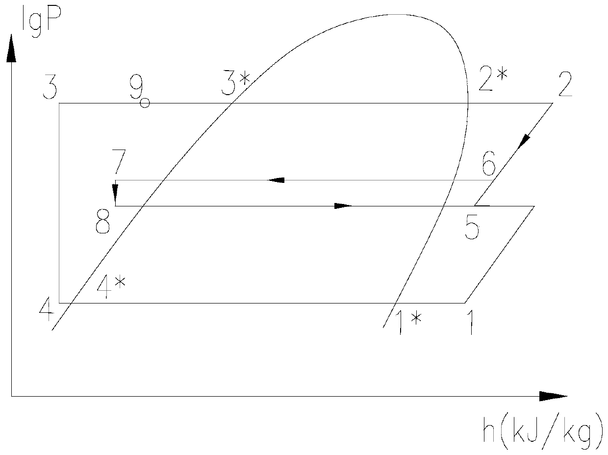
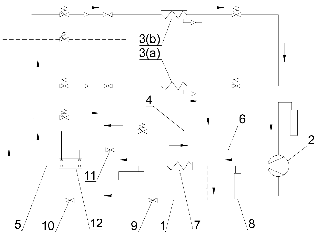
[0030] see figure 2 In this embodiment, the defrosting device that utilizes the defrosting medium to supercool the refrigerant in the main pipeline is integrated in the refrigeration system, and includes the evaporator 3 (a ) in the defrosting pipeline 1, the main pipeline cooler for supercooling the refrigerant in the refrigeration main pipeline 5, and the defrosting outlet pipeline 4 for transporting the defrosted refrigerant to the main pipeline cooler , the defrosting pipeline 1 is connected to the refrigeration main pipeline 5, the head end of the defrosting liquid outlet pipeline 4 is connected to the outlet of the evaporator 3 (a) to be defrosted, and the end is connected to the main pipeline cooler of the import.

[0031] see figure 2 , the first end of the defrosting pipeline 1 is connected between the compressor 2 and the condenser 7, and the end is connected to the inlet of the evaporator 3 (a) to be defrosted. In this way, the gas refrigerant with a high entha...

Embodiment 2

[0043] The difference from Embodiment 1 is that in this embodiment, the liquid refrigerant condensed by the condenser 7 is diverted to the evaporator 3 (a) to be defrosted through the defrosting pipeline 1, and the liquid refrigerant is used as the defrosting medium, exothermic to melt frost on the evaporator.

[0044] Of course, the defrosting medium can also be a vapor-liquid mixture refrigerant, and the vapor-liquid mixture refrigerant can be obtained by mixing gas refrigerant and liquid refrigerant; in addition, the vapor-liquid mixture refrigerant can also be obtained by The liquid refrigerant is throttled and then absorbed heat.


PUM


Abstract

The invention discloses a defrosting method and device for supercooling a refrigerant in a refrigeration main pipeline by using a defrosting medium. The defrosting method comprises the following stepsthat the refrigerant in the refrigeration main pipeline is shunted to an evaporator to be defrosted, and the shunted refrigerant used as a defrosting medium releases heat to melt frost on the evaporator; the refrigerant obtained after defrosting is conveyed to a main pipeline cooler, the refrigerant obtained after defrosting is subjected to evaporation and heat absorption in the main pipeline cooler to supercool the refrigerant in the refrigeration main pipeline, wherein the evaporation temperature in the main pipeline cooler is higher than the evaporation temperature of the evaporator beingrefrigerated; and the refrigerant completing the supercooling work is conveyed back to a compressor for circulating work. According to the method and the device, the refrigerant in the refrigeration main pipeline is supercooled by the refrigerant obtained after defrosting, the refrigerating capacity of the refrigerant obtained after defrosting is fully utilized, the heat absorption capacity of therefrigerant in the refrigeration main pipeline is improved, and the refrigerating capacity of the system is increased.

Description

technical field [0001] The invention relates to a defrosting technology of a refrigeration system, in particular to a defrosting method and device for supercooling a main pipeline refrigerant by using a defrosting medium. Background technique [0002] During the operation of the refrigeration system, when the evaporation temperature is lower than 0°C, frost will appear on the evaporator, which will lead to a decrease in heat exchange and refrigeration efficiency, so defrosting treatment is required. [0003] The existing defrosting methods mainly include refrigerant defrosting and non-refrigerant defrosting. Among them, the refrigerant defrosting technology is an energy-saving technology. Defrosting; of course liquid refrigerants also exist as defrosting medium. In the existing defrosting process, when the defrosting medium passes through the evaporator, it will release heat to defrost, and then lead to the cooling evaporator for evaporative refrigeration. For example, in ...

Claims


Application Information

Patent Timeline
Patent Type & Authority Applications(China)
IPC IPC(8): F25B47/02F25B49/02
CPCF25B47/02F25B49/02F25B2347/022
Inventor 李浩权肖波黄隆胜吴耀森胡光华马道宽刘军卢素珊叶开愚
Owner GUANGDONG PROVINCE MODERN AGRI EQUIP RES INST
Why Eureka
Try Eureka