A loading fixture device for cross-shaped specimen biaxial equal load and non-equal load fatigue test

A technology of fatigue test and fixture device

Active Publication Date: 2021-08-17
NANJING UNIV OF AERONAUTICS & ASTRONAUTICS
View PDF2 Cites 0 Cited by
  • Summary
  • Abstract
  • Description
  • Claims
  • Application Information

AI Technical Summary

Problems solved by technology

[0002] The cross-shaped biaxial fatigue test can be used to analyze the fatigue performance of materials under complex stress states, but the biaxial fatigue testing machine is expensive, the test control is difficult, and the test cost is high

Method used


Image

  • A loading fixture device for cross-shaped specimen biaxial equal load and non-equal load fatigue test
  • A loading fixture device for cross-shaped specimen biaxial equal load and non-equal load fatigue test
  • A loading fixture device for cross-shaped specimen biaxial equal load and non-equal load fatigue test

Examples


Embodiment 1

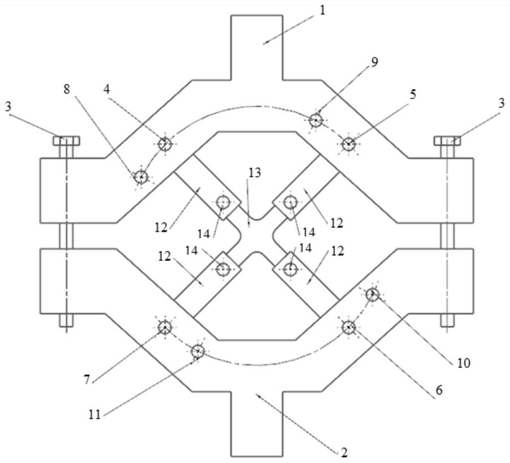
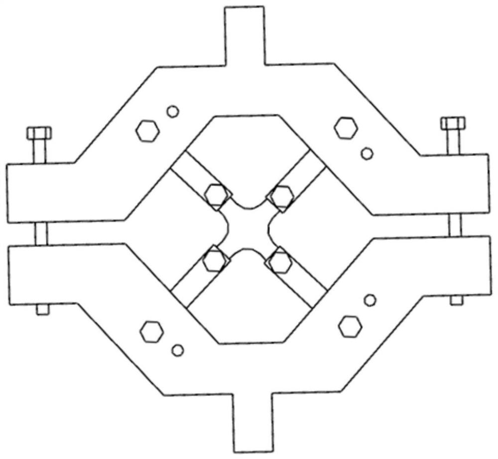
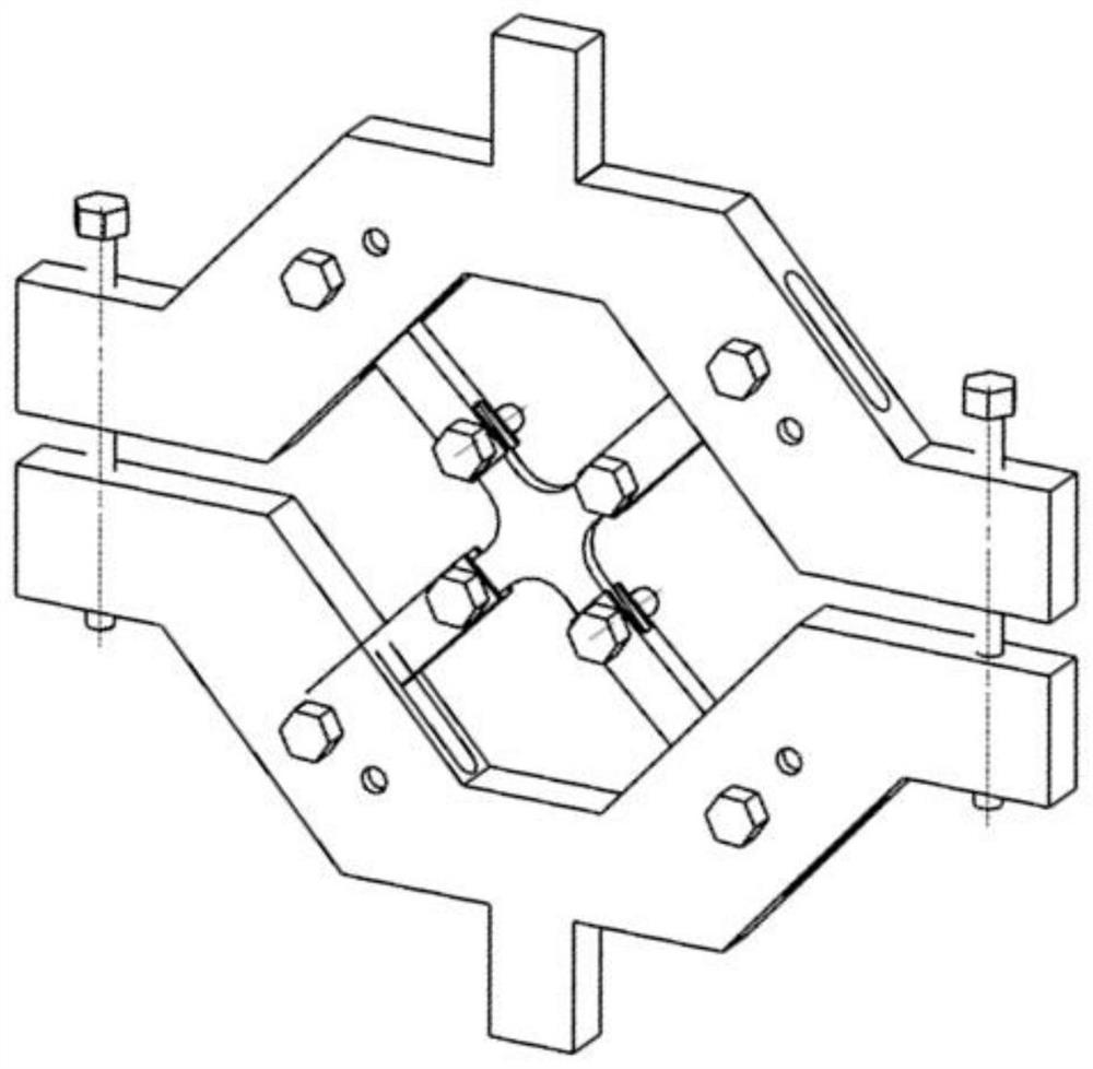
[0026] Embodiment 1: as figure 1 , figure 2 and image 3 As shown, the present invention proposes a loading fixture device for biaxial equal-load and non-equal-load fatigue tests of a cross-shaped test piece, including a cross-shaped test piece 13, an upper splint 1 and a lower splint 2 correspondingly distributed up and down, and a cross-shaped test piece. The piece 13 is set in the accommodation cavity formed between the upper splint 1 and the lower splint 2, and four symmetrically distributed tie rods 12 are arranged between the upper splint 1 and the lower splint 2, and the cross-shaped test piece 13 is connected to the upper splint respectively through the tie rods 12. 1. The lower splint 2 is mated and connected. The two ends of the upper splint 1 and the lower splint 2 are provided with positioning guide rods 3. The upper splint 1 is tightly connected with the lower splint 2 through the positioning guide rod 3 to fix the upper splint 1 and the lower splint. 2. It can...

Embodiment 2

[0030] Embodiment 2: The line connecting the centers of the fifth round hole 8 and the seventh round hole 10 is 60 degrees to the center line of the upper splint 1 and the lower splint 2, and the rest are the same as in the first embodiment.

Embodiment 3

[0031] Embodiment 3: The upper splint 1 and the lower splint 2 are provided with a rectangular tie rod installation through groove corresponding to the tie rod 12, and the tie rod 12 is installed in the tie rod installation through groove, and the tie rod 12 is connected to the upper splint 1 and the lower splint 2 by bolts 14. Tightly connected, the rest are the same as in Example 1.


PUM


Abstract

The invention discloses a loading fixture device for biaxial equal-load and non-equal-load fatigue tests of a cross-shaped test piece, which comprises a cross-shaped test piece, upper and lower splints correspondingly distributed up and down, and the cross-shaped test piece is arranged on the upper and lower splints. In the accommodation cavity formed between the splint and the lower splint, four symmetrically distributed pull rods are arranged between the upper splint and the lower splint, and the cross-shaped test piece is respectively connected to the upper splint through the pull rods. . The lower splint is mated and connected, positioning guide rods are provided at both ends of the upper splint and the lower splint, and the upper splint is fastened to the lower splint through the positioning guide rods. Aiming at how to solve the technical requirement of "the existing biaxial fatigue testing machine is expensive, the test control is difficult, and the test cost is high", the invention realizes the uniaxial fatigue test as a whole by designing the loading fixture for the cross-shaped test piece. The cross-shaped test piece is loaded biaxially on the machine, which effectively controls the test cost and reduces the technical effect of the test difficulty.

Description

technical field [0001] The invention relates to a loading fixture device for biaxial equal-load and non-equal-load fatigue tests of a cross-shaped specimen, which is used to realize biaxial equal-load and non-equal-load fatigue loading on a uniaxial tension-compression fatigue testing machine. The axial loading on the machine can simultaneously realize biaxial equal-load and non-equal-load fatigue loading on the cross-shaped test piece, which belongs to the technical field of mechanical manufacturing. Background technique [0002] The cross-shaped biaxial fatigue test can be used to analyze the fatigue performance of materials under complex stress states, but the biaxial fatigue testing machine is expensive, the test control is difficult, and the test cost is high. Therefore, it is necessary to design the loading fixture for the cross-shaped specimen, realize the biaxial loading of the cross-shaped specimen on the uniaxial fatigue testing machine, effectively control the tes...

Claims


Application Information

Patent Timeline
Patent Type & Authority Patents(China)
IPC IPC(8): G01N3/04
CPCG01N3/04G01N2203/0016G01N2203/0073G01N2203/0254G01N2203/0272
Inventor 吴志荣王帅强潘磊宋迎东
Owner NANJING UNIV OF AERONAUTICS & ASTRONAUTICS
Why Eureka
Try Eureka