
A test device for buried pipelines across seismic faults

A technology for testing devices and buried pipelines, which is applied in measuring devices, mechanical devices, and testing of machine/structural components. smooth effect

Active Publication Date: 2022-05-31
SOUTHWEST PETROLEUM UNIV
View PDF8 Cites 1 Cited by
  • Summary
  • Abstract
  • Description
  • Claims
  • Application Information

AI Technical Summary

Problems solved by technology

[0003] Purpose of the present invention: To overcome the problem that the existing test device for buried pipelines across seismic faults simulates a single type of fault and rarely studies the dip angle of the fault, and provides a more adaptable device for multi-type fault pipe-soil test

Method used


Image

  • A test device for buried pipelines across seismic faults
  • A test device for buried pipelines across seismic faults
  • A test device for buried pipelines across seismic faults

Examples


Embodiment 1

[0026] Example 1: Positive and reverse fault test process

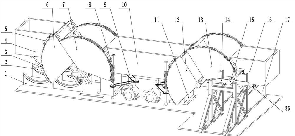
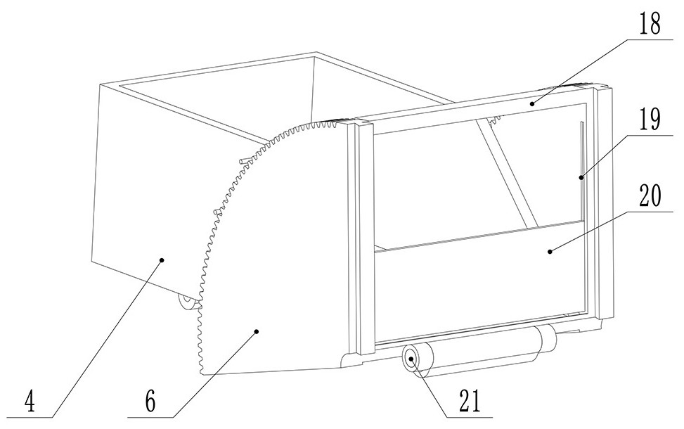
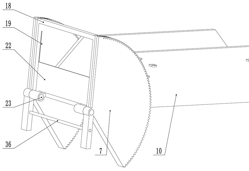
[0027] like Figure 1 to Figure 4 As shown, the fixed earth box 10 is anchored to the fixed support 11 . The left side of the fixed earth box 10 is installed with an inclination adjustment worm gear left 2 7, and the vertically movable earth box 4 is installed with an inclination adjustment worm wheel left 1 6. The left one 6 and the left two 7 of the inclination adjustment worm gear each contain two pieces, which are respectively arranged on both sides of the vertically moving soil box 4 and the fixed soil box 10. . A dovetail groove is radially processed between the left one 6 and the second left 7 of the inclination angle adjusting worm gear, and the two worm gears can slide radially after being assembled. Use pin one 21 to pass through the vertical moving earth box 4 and the left one 6 of the inclination adjustment worm gear, and the second pin 23 to pass through the fixed earth box 10 and the left two 7 inclin...

Embodiment 2

[0032] Example 2: Strike-slip (translational) fault test process

[0033] like figure 1 As shown, the bottom of the horizontally moving earth box 16 is equipped with a second limiting roller 35 , and the second limiting roller 35 drives the horizontally moving soil box 16 to move in translation along the limiting rail 17 . like Figure 7 , Figure 8 As shown, the right side of the fixed earth box 10 is installed with the right one 12 and the right three 26 of the inclination adjustment worm gear, which are installed on the outside and the inside of the fixed earth box 10 respectively, and are connected by the second tie rod 27, and the third earth retaining plate 25 is welded to the right one of the inclination adjustment worm gear. 12 and the second tie rod 27; the outside and the inside of the horizontally moving earth box 16 are respectively installed with the right second 13 and the right fourth 28 of the inclination adjustment worm gear, which are connected by the third...


PUM


Abstract

The invention relates to a test device for a buried pipeline across an earthquake fault, which is used for simulating the deformation process and stress situation of the buried pipeline under the action of an earthquake fault, and applies a fault-type soil external load to the buried pipeline by means of the device. It includes vertically moving boxes, fixed boxes and horizontally moving boxes arranged in sequence to form test devices for forward (reverse) faults and strike-slip faults, respectively. The test piping is arranged along the length of the box and runs through the three boxes. The tank is equipped with an inclination adjusting worm gear, and the stepping motor is used to drive the worm and worm gear mechanism to realize the transformation of forward and reverse faults and the adjustment of the inclination angle of the fault. The vertically moving box is lifted by the hydraulic cylinder, and the horizontally moving box is placed on the limit rail and pushed by the side hydraulic cylinder. The invention can simulate three types of faults, forward, reverse and strike-slip, and can also realize the simulation research on the dip angle of the fault, and has strong adaptability.

Description

technical field [0001] The invention relates to a mid-span fault buried pipeline experimental device in the field of oil and natural gas, which is suitable for simulating the deformation process and stress situation of the buried pipeline under the action of earthquake faults. load, specifically a pipe-soil model test device. Background technique [0002] As one of the most efficient transportation methods for oil and natural gas, pipelines have the characteristics of small footprint, no impact on traffic and small ground operations. Oil and gas pipelines have long transportation distances, and the geological environment along the line is complex and changeable. Some pipeline sections may encounter geological disasters such as earthquake faults, and geotechnical activities caused by severe geological disasters can easily cause pipeline deformation and fracture. According to the relative motion relationship between the two sides of the fault, it can be divided into different...

Claims


Application Information

Patent Timeline
Patent Type & Authority Patents(China)
IPC IPC(8): G01N19/00G01M99/00
CPCG01N19/00G01M99/00
Inventor 张杰陈阳汪浩瀚于春雨周兆明
Owner SOUTHWEST PETROLEUM UNIV
Learn More