Steel bridge fatigue crack monitoring device and method

A fatigue crack and monitoring device technology, which is applied in measuring devices, using sound waves/ultrasonic waves/infrasonic waves to analyze solids, and using sound waves/ultrasonic waves/infrasonic waves for material analysis, etc., can solve the problem of affecting the service life of steel structure bridges and the inability to understand the continuity of fatigue cracks Development situation and other issues to achieve the effect of improving service life and operational safety

Inactive Publication Date: 2020-08-14
JSTI GRP CO LTD
View PDF6 Cites 0 Cited by
  • Summary
  • Abstract
  • Description
  • Claims
  • Application Information

AI Technical Summary

Problems solved by technology

Because fatigue cracks will enter a period of rapid growth after initiation, the growth of fatigue cracks will seriously affect the service life of steel structure bridges
[0003] In the prior art, the detection of fatigue cracks in steel bridges usually uses ultrasonic, magnetic powder, magnetic flux and other methods for regular detection. However, regular detection can only detect the periodic static results of cracks, but cannot understand the continuous development of fatigue cracks during the detection gap. Happening

Method used


Image

  • Steel bridge fatigue crack monitoring device and method
  • Steel bridge fatigue crack monitoring device and method
  • Steel bridge fatigue crack monitoring device and method

Examples


Embodiment Construction

[0039] The following will clearly and completely describe the technical solutions in the embodiments of the present invention with reference to the accompanying drawings in the embodiments of the present invention. Obviously, the described embodiments are only some, not all, embodiments of the present invention.

[0040] Ultrasonic time-of-flight diffraction (TOFD) is an ultrasonic monitoring method for monitoring defects by using the diffraction waves emitted by sound waves at the "end angles" and "end points" of internal defects in the test piece. It can realize defect monitoring, quantification and positioning. Strong detection ability, high positioning accuracy, easy operation, digital storage, safety and environmental protection and other advantages.

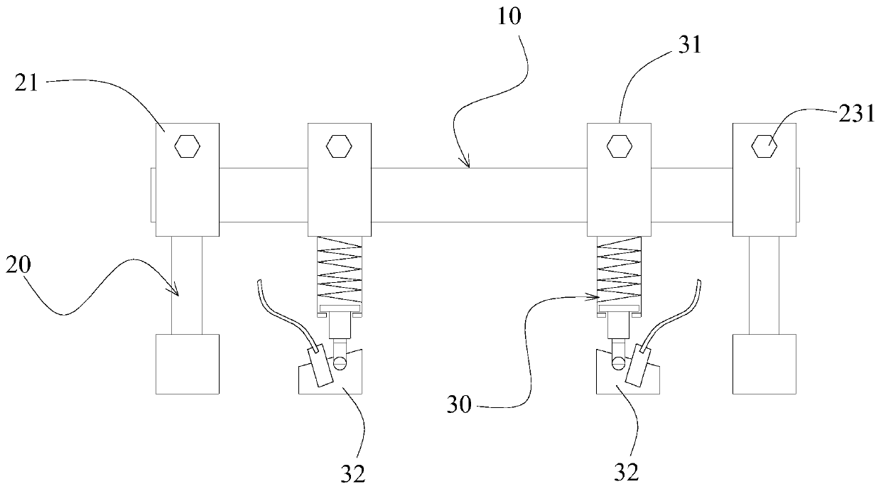
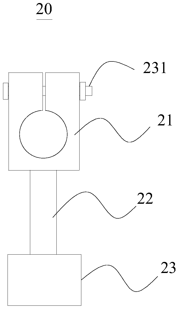
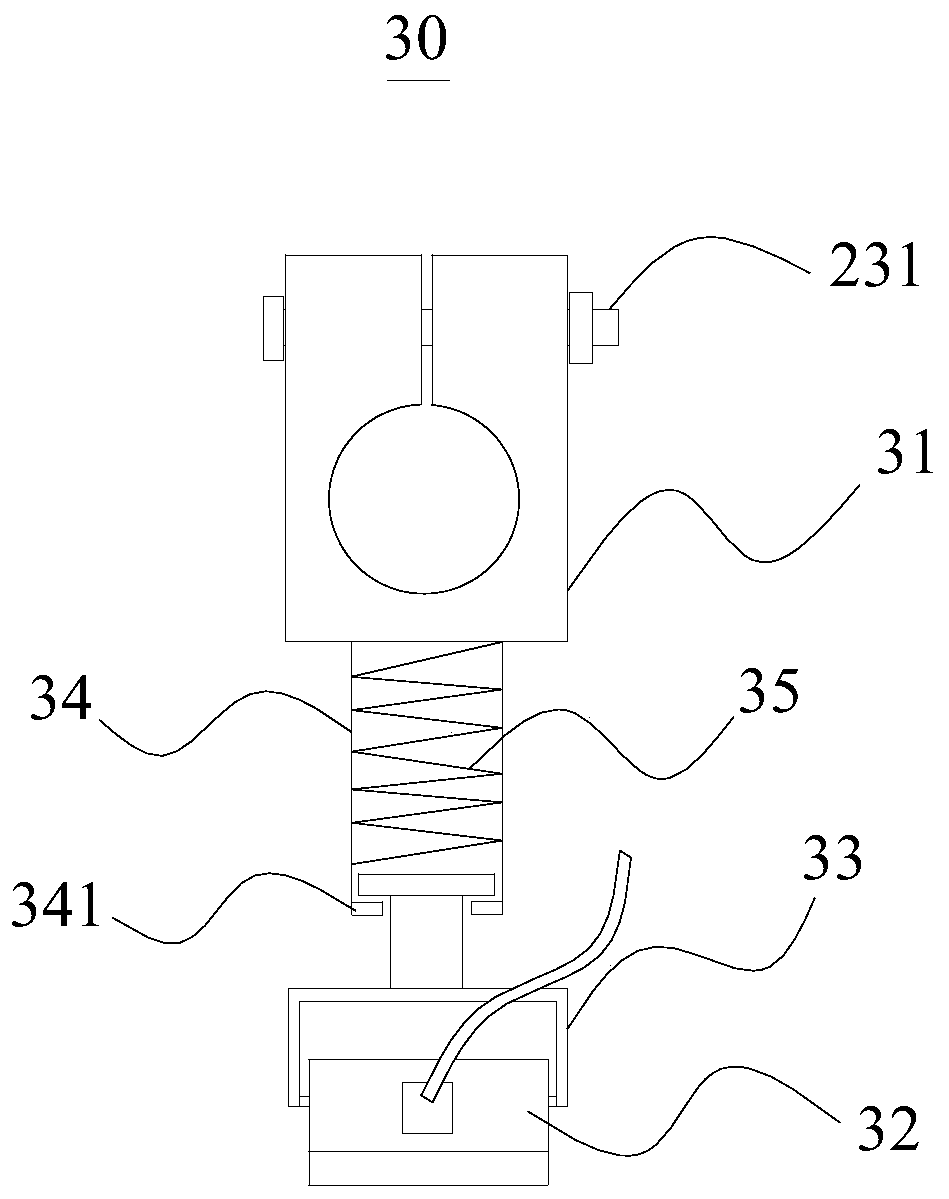
[0041] Such as Figures 1 to 4 The shown steel bridge fatigue crack monitoring device includes:

[0042] sliding guide rod 10;

[0043] The positioning mechanism 20 has a first positioning buckle 21 on the positioning mec...


PUM


Abstract

The invention relates to the technical field of steel bridge fatigue crack monitoring, in particular to a steel bridge fatigue crack monitoring device. The device comprises a sliding guide rod; at least two positioning mechanisms which are provided with at least two first positioning buckles, wherein the sliding guide rod is sleeved by the first positioning buckles on the two positioning mechanisms, and the bottoms are fixedly connected with the surface of the steel plate at a fatigue crack; a monitoring mechanism which is provided with a second positioning buckle and TOFD probes, wherein thesecond positioning buckle is arranged on the sliding guide rod in a sleeving mode, the TOFD probes are connected with the second positioning buckle, and the bottoms of the two TOFD probes make contactwith the steel plates on the two sides of the crack. Real-time monitoring of cracks is achieved through the positioning mechanisms and the monitoring mechanism which are arranged on the sliding guiderod. Multiple monitoring devices are arranged at the two ends and the middle position of the crack, and changes of the crack in the length direction and the depth direction can be monitored, so the real-time dynamic tracking of the steel bridge crack is achieved, and the durability and the operation safety of the steel bridge are improved. The invention further provides a steel bridge fatigue crack monitoring method.

Description

technical field [0001] The invention relates to the technical field of steel bridge fatigue crack monitoring, in particular to a steel bridge fatigue crack monitoring device and method. Background technique [0002] Fatigue cracks in steel bridges refer to the cracks that occur under the repeated loads of vehicles during the operation of steel bridges, which have great safety hazards and are one of the main diseases of steel bridges. Because fatigue cracks will enter a period of rapid growth after initiation, the growth of fatigue cracks will seriously affect the service life of steel structure bridges. [0003] In the prior art, the detection of fatigue cracks in steel bridges usually uses ultrasonic, magnetic powder, magnetic flux and other methods for regular detection. However, regular detection can only detect the periodic static results of cracks, but cannot understand the continuous development of fatigue cracks during the detection gap. Condition. Therefore, the de...

Claims


Application Information

Patent Timeline
Patent Type & Authority Applications(China)
IPC IPC(8): G01N29/07G01N29/22G01N29/28G01B17/00
CPCG01B17/00G01N29/07G01N29/223G01N29/28G01N2291/011G01N2291/0234G01N2291/0289G01N2291/044G01N2291/105
Inventor 王贤强张建东吴赞平刘朵徐海虹林毅华春丽李昊杨羿杜元陈欣张东亮孙敏黄健华
Owner JSTI GRP CO LTD
Why Eureka
Try Eureka