High-altitude parabolic monitoring method

A high-altitude parabola, building technology, used in surveying devices, surveying and navigation, photogrammetry/video surveying, etc.

Active Publication Date: 2020-08-14
HUNAN LIANZHI BRIDGE & TUNNEL TECH
View PDF8 Cites 8 Cited by
  • Summary
  • Abstract
  • Description
  • Claims
  • Application Information

AI Technical Summary

Problems solved by technology

[0008] The purpose of the present invention is to provide a high-altitude paraboli

Method used


Image

  • High-altitude parabolic monitoring method
  • High-altitude parabolic monitoring method
  • High-altitude parabolic monitoring method

Examples


Embodiment 1

[0053] see Figure 1 to Figure 6 , a high-altitude parabolic monitoring method, the present embodiment is applied to high-altitude parabolic monitoring and confirmation of parabolic points.

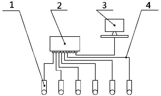
[0054] A kind of high-altitude parabolic monitoring method adopts such as figure 1 The high-altitude parabolic monitoring system shown is for parabolic monitoring. The high-altitude parabolic monitoring system is set up with reference to the existing technology, including camera 1, core switch 2, control center 3 and network cable 4. The control center 3 has built-in settings for high-altitude parabolic monitoring. Program, all the cameras 1 of a building are connected to the core switch 2 through the network cable 4, and the control center 3 is also connected to the core switch 2 through the network cable 4, and all the devices together form a high-speed local area network. In this embodiment, the camera adopts a wide-angle high-definition camera Performing high-altitude parabolic monit...

Embodiment 2

[0082] see Figure 7 to Figure 10 , a high-altitude parabolic monitoring method, the present embodiment is applied to high-altitude parabolic monitoring and confirmation of parabolic points.

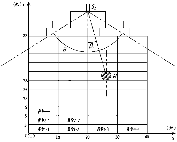
[0083] The difference between this embodiment and Embodiment 1 is that two cameras are set up on the top of the building, which are respectively and webcam , when the number of cameras is two or more, the cameras are combined in pairs for real-time video monitoring, and the first The angle formed by the center line of the viewing angle of a camera and the vertical line ;Such as Figure 7 As shown, the lower left corner of the building is taken as the origin of the coordinate system, the positive direction of the x-coordinate axis is horizontal to the right, and the positive direction of the coordinate axis y is vertical upward, and a unit length on the coordinate axis corresponds to a distance value of 1 meter, where ,Camera coordinate of is (8,38), camera coordinate of i...


PUM


Abstract

The invention provides a high-altitude parabolic monitoring method. The method comprises the following steps: erecting a camera at the top of a building according to the size of the building, monitoring the side parabolic condition of the building, and sending a video file to a control center; enabling the control center to judge whether a parabolic condition occurs or not through comparison of adjacent picture frames, finding out a timestamp of the picture frame where the parabolic target occurs for the first time, fining out images shot by all the cameras at the moment, and carrying out binarization processing to obtain a binarized image corresponding to each camera; establishing a rectangular coordinate system corresponding to the room number along the building monitoring surface, determining the coordinate corresponding to each camera and the geometrical relationship between the parabolic point and the camera, calculating the parabolic coordinate corresponding to the parabolic point in combination with the binarized image, and obtaining the room number corresponding to the parabolic coordinate. The rectangular coordinate system is established along the monitoring side surface of the building, the room number of the parabolic object can be quickly positioned according to the calculated parabolic object coordinate, and high-altitude parabolic object tracking, education and responsibility investigation are facilitated.

Description

technical field [0001] The invention relates to the technical field of image monitoring and processing, in particular to a high-altitude parabolic monitoring method. Background technique [0002] High-altitude parabolic phenomenon is called "pain hanging over the city", which is an extremely uncivilized behavior, which can easily bring social harm and cause major social impact; in response to high-altitude parabolic phenomenon, various regions have issued regulations prohibiting high-altitude parabolic phenomena Laws and regulations are in place to ensure the safety of people's lives and property, but there are still problems such as difficulty in monitoring and obtaining evidence. [0003] In order to protect the privacy of residents, the existing automatic monitoring method for high-altitude parabolic objects is mainly to set a looking-up monitoring camera on the ground downstairs of the building for 24-hour video storage and monitoring. This method has the following prob...

Claims


Application Information

Patent Timeline
IPC IPC(8): G06K9/00G06F16/783H04N5/76H04N7/18G01C11/02
CPCG06F16/783H04N7/181H04N5/76G01C11/025G06V20/52
Inventor 周俊华雷孟飞赵莉
Owner HUNAN LIANZHI BRIDGE & TUNNEL TECH
Why Eureka
Try Eureka