Eureka AIR delivers breakthrough ideas for toughest innovation challenges, trusted by R&D personnel around the world.

Bidirectional magnetic levitation sound wave motor device

A magnetic levitation and sound wave technology, applied in electromechanical devices, holding devices using magnetic attraction or thrust, magnetic circuits, etc., can solve problems such as no axial telescopic function, large changes in motor shaft swing, and difficulty in repair, avoiding the need for Short service life, stable power transmission process, improved cleaning effect

Pending Publication Date: 2020-08-14
KERUI TECH (DONGGUAN) CO LTD
View PDF0 Cites 5 Cited by
  • Summary
  • Abstract
  • Description
  • Claims
  • Application Information

AI Technical Summary

Problems solved by technology

The motors in existing electric toothbrushes generally need to install springs or torsion bars similar to torsion springs. During use, such structures are easily damaged and difficult to repair, so the service life of the motor often depends on how long the above structures can be used
And adopting the above-mentioned structural design makes the load capacity of the motor low, the torque that can be transmitted by the motor per unit volume is small, and the swing amplitude of the motor shaft varies greatly when bearing different loads, and the use effect is not stable enough
[0004] In addition, the motion trajectory of existing electric toothbrushes generally swings radially left and right, without axial telescopic function, but people brush their teeth in daily life, not only need to swing up and down to clean teeth (radial swing), but also need to move left and right (axial telescopic ) to achieve the purpose of all-round cleaning, how to effectively solve this problem has always been a difficult problem for those skilled in the art to break through

Method used


Image

  • Bidirectional magnetic levitation sound wave motor device
  • Bidirectional magnetic levitation sound wave motor device
  • Bidirectional magnetic levitation sound wave motor device

Examples


Embodiment Construction

[0035] In order to enable those skilled in the art to better understand the technical solutions of the present invention, the present invention will be further described in detail below in conjunction with the accompanying drawings.

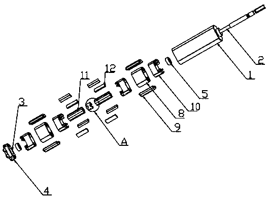
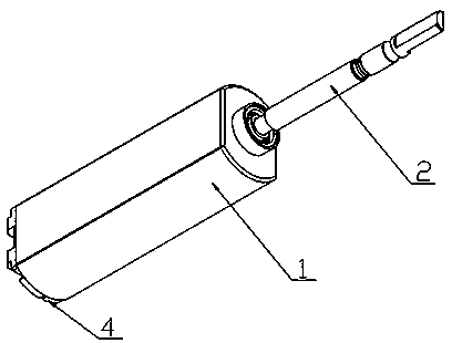
[0036] The present invention provides such Figure 1-14 A two-way magnetic levitation acoustic wave motor device shown includes a motor housing 1 and a motor shaft 2, the motor shaft 2 is arranged at the axis of the motor housing 1, and the bottom end of the motor housing 1 is provided with an end cover 4, so that The shaft centers of the motor casing 1 and the end cover 4 are provided with shaft holes 3, the motor shaft branch 2 runs through the two shaft holes 3, and the connection between the motor shaft branch 2 and the shaft hole 3 is provided with a bearing 5, so The inside of the motor housing 1 is provided with a transmission unit, the transmission unit is composed of a stator assembly 6 and a rotor assembly 7, and the rotor assembly 7 is...


PUM


Abstract

The invention discloses a bidirectional magnetic levitation sound wave motor device which comprises a motor shell and a motor shaft branch, the motor shaft branch is arranged at the axis of the motorshell, an end cover is arranged at the bottom end of the motor shell, shaft holes are formed in the axis of the motor shell and the axis of the end cover, and the motor shaft branch penetrates throughthe two shaft holes. According to the invention, motion transmission is realized through an electromagnetic effect; a torsion bar and other elastic structures do not need to be installed; on one hand, the situation that the service life of the motor is short due to the fact that the elastic structure is easily damaged in use is avoided; on the other hand, the motor in unit volume can transmit torque with a larger numerical value; when the device is applied to an electric toothbrush, the weight of the electric toothbrush can be reduced, the up-and-down telescopic movement is closer to the tooth brushing feeling in daily life while left and right swinging is carried out, the cleaning effect is greatly improved, the user experience is improved, and the blank that no axial telescopic movementexists except radial left-and-right swinging in the market is filled up.

Description

technical field [0001] The invention relates to the technical field of motors, in particular to a two-way magnetic levitation acoustic wave motor device. Background technique [0002] With the continuous improvement of people's living standards, electric toothbrushes have begun to enter people's daily life, replacing traditional toothbrushes to achieve a more ideal and convenient brushing effect. [0003] Existing electric toothbrushes are usually driven by a motor, which cleans the teeth through the vibration of the toothbrush head. The motors in existing electric toothbrushes generally need to be equipped with springs or torsion bars similar to torsion springs. Such structures are easily damaged during use and are not easy to repair. Therefore, the service life of the motor often depends on how long the above structures can be used. And adopting the above-mentioned structural design makes the bearing capacity of the motor low, the torque that can be transmitted by the mot...

Claims


Application Information

Patent Timeline
Patent Type & Authority Applications(China)
IPC IPC(8): H02K1/12H02K1/14H02K1/27H02K1/34H02K3/28H02K33/00H02N15/00A61C17/34
CPCH02K1/12H02K1/14H02K1/146H02K1/2706H02K1/34H02K3/28H02K33/00H02N15/00A61C17/3472A61C17/3445A61C17/3454
Inventor 罗东胜晏木
Owner KERUI TECH (DONGGUAN) CO LTD
Why Eureka
Eureka Blog
Learn More