Switched reluctance motor

A technology of switched reluctance motor and motor body, which is applied in the direction of electrical components, electromechanical devices, mechanical equipment, etc., which can solve the problems of poor coaxiality, output shaft disassembly damage, energy loss, etc., and reduce the poor coaxiality of connections , fast and easy disassembly, and the effect of improving the service life

Inactive Publication Date: 2020-08-14
淮南威凯机械设备有限公司
View PDF0 Cites 7 Cited by
  • Summary
  • Abstract
  • Description
  • Claims
  • Application Information

AI Technical Summary

Problems solved by technology

[0005] In order to make up for the deficiencies of the existing technology, there are many ways to solve the transmission connection of the switched reluctance motor in the prior art, such as the hole shaft key connection, the transmission belt connection, the gear mesh connection, etc., wherein the transmission belt connection and the gear mesh connection are different. The shaft connection method needs to involve the transmission method of relative motion. There will be more energy loss in the process of non-coaxial connection transmission. The most efficient and energy-saving connection method is such as hole shaft key connection. This type of connection method is coaxial Connection method, but during the connection process, the coaxiality between the output shaft of the motor body and the transmission shaft is likely to be poor. When it is necessary to disassemble the transmission shaft and the output shaft of the motor body, the connection is relatively tight on the one hand. It is difficult to disassemble, and employees often knock and disassemble. On the other hand, the hole shaft often uses an interference fit method. During the disassembly process, the output shaft of the drive shaft and the motor body is prone to disassembly damage, further reducing the output shaft of the motor body. To solve problems such as the connection coaxiality between transmission shafts, the present invention proposes a switched reluctance motor

Method used


Image

  • Switched reluctance motor
  • Switched reluctance motor
  • Switched reluctance motor

Examples


Embodiment approach

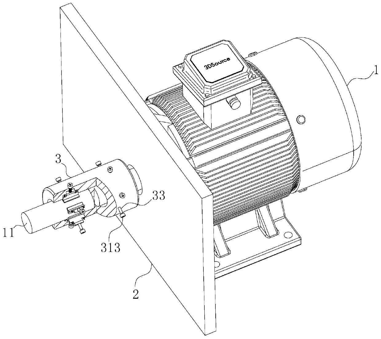
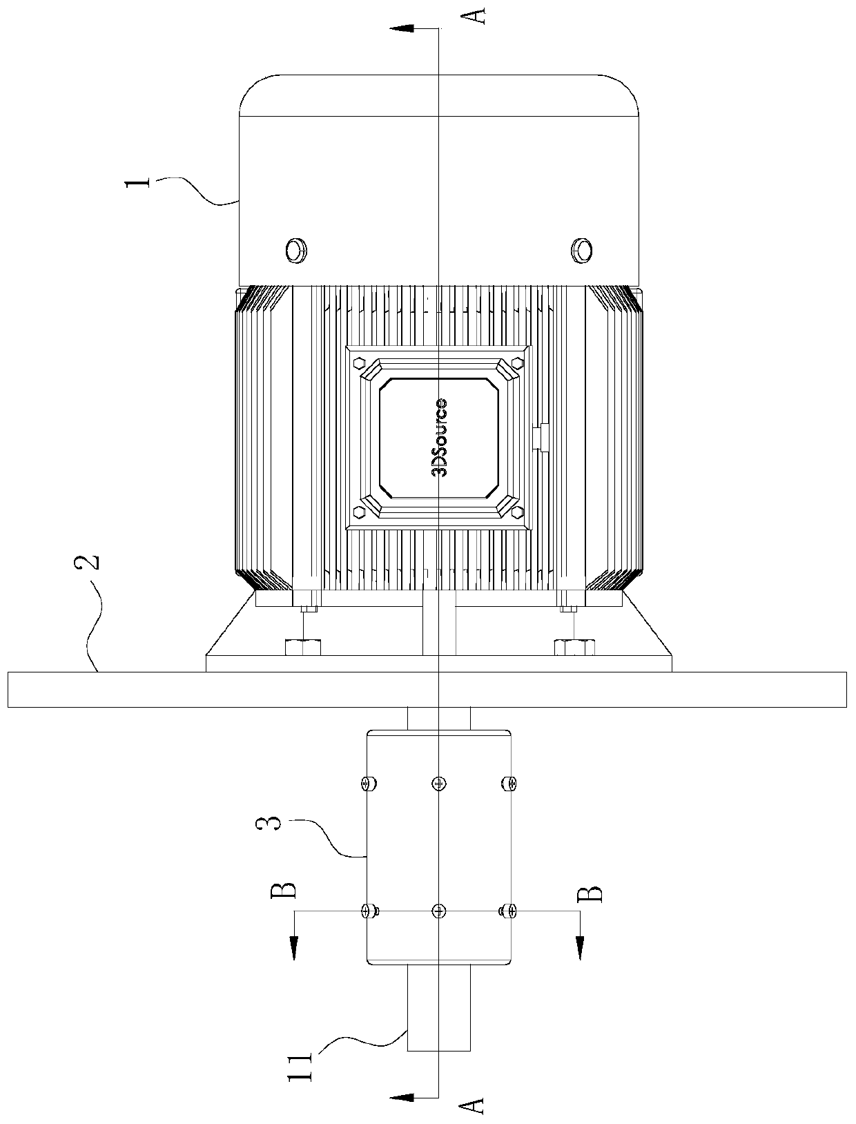
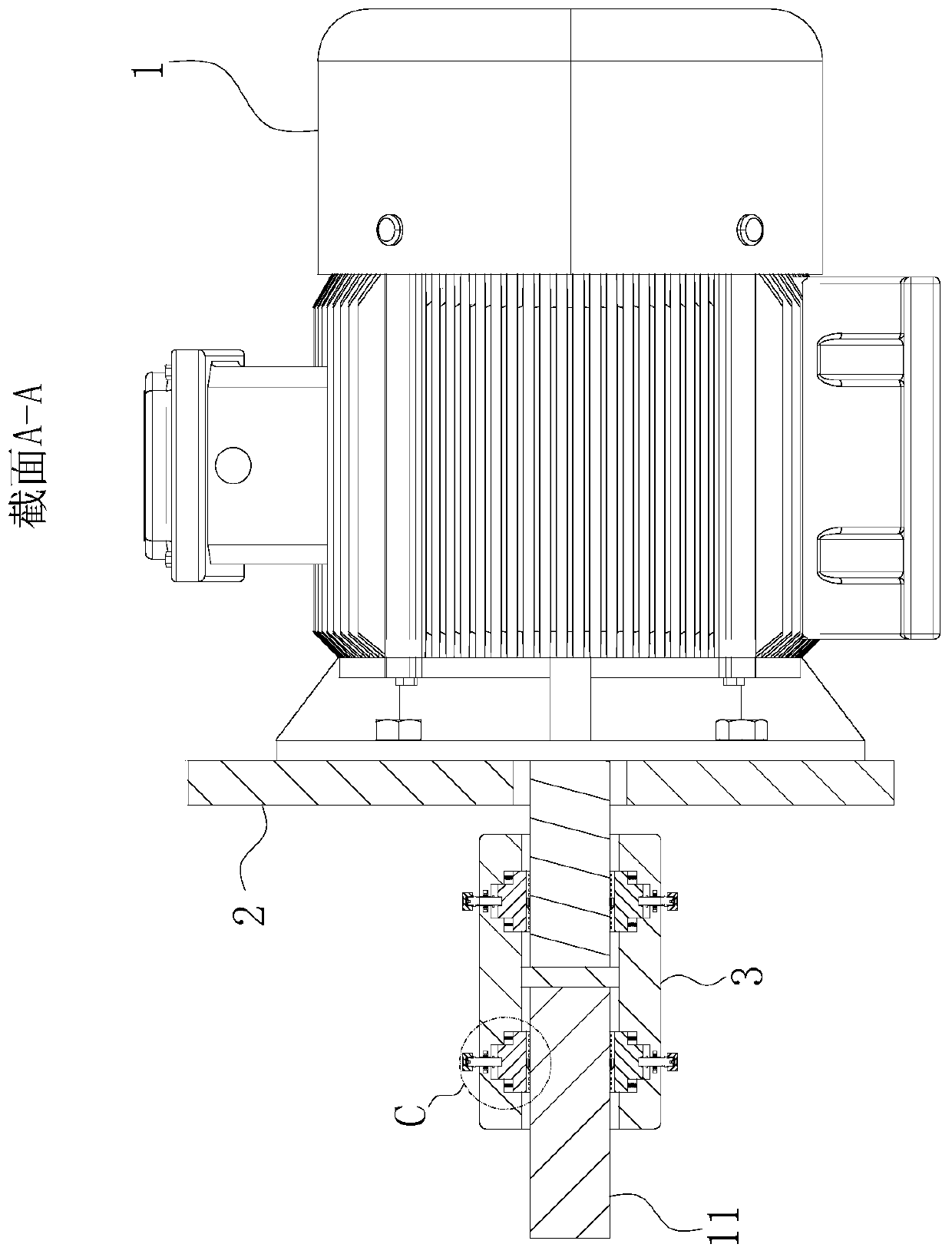
[0027] As an embodiment of the present invention, the fixing plate 32 is provided with a second installation groove on one side of the output shaft or the transmission shaft 11 of the motor body 1; block 37; the first telescopic rod 38 is fixedly connected between the briquetting block 37 and the groove bottom of the corresponding second installation groove, and the piston rod of the first telescopic rod 38 and the corresponding briquetting block 37 are fixed to each other. connection; the connecting sleeve 3 is provided with evenly arranged limiting grooves at the positions of the threaded adjustment holes; the inside of the limiting grooves are all slidably connected to the limiting block 39; the limiting block 39 and the groove of the corresponding limiting groove The positions between the bottoms are fixedly connected with the second telescopic rods 310, and the second telescopic rods 310 and the corresponding first telescopic rods 38 are connected to each other; when worki...


PUM


Abstract

The invention belongs to the technical field of motors, and particularly relates to a switched reluctance motor which comprises a motor body, a mounting plate and a connecting sleeve. The left side end surface of the motor body is fixedly connected with the mounting plate; the connecting sleeve is arranged on the left side of an output shaft of the motor body; mounting through holes are formed inthe left end face and the right end face of the connecting sleeve, and an output shaft of the motor body is inserted into the mounting through holes. A transmission shaft is inserted into the mountingthrough holes and located on the end face of the left side of the connecting sleeve. According to the invention, the rapid and coaxial connection between the output shaft and the transmission shaft of the motor body is effectively realized, the problem of poor connection coaxiality is effectively reduced through a fine adjustment mechanism, rapid and light disassembly can be realized through a threaded screwing fixing structure, the disassembly damage problem is avoided, and the service life of the motor body is prolonged.

Description

technical field [0001] The invention belongs to the technical field of motors, in particular to a switched reluctance motor. Background technique [0002] Switched reluctance motor is a new type of speed regulating motor. The speed regulating system has the advantages of both DC and AC speed regulating systems. It is the latest generation of stepless speed regulating system following frequency conversion speed regulating system and brushless DC motor speed regulating system. Its structure is simple and firm, with wide speed regulation range, excellent speed regulation performance, high efficiency in the entire speed regulation range, and high system reliability. It mainly includes switched reluctance motors, power converters, controllers and position detection. The controller consists of four parts, the controller contains the control circuit and the power converter, and the rotor position detector is installed at one end of the motor. [0003] There are many ways of transm...

Claims


Application Information

Patent Timeline
Patent Type & Authority Applications(China)
IPC IPC(8): H02K7/00F16D1/04
CPCF16D1/04H02K7/003
Inventor 沈墅王鹏李河
Owner 淮南威凯机械设备有限公司
Why Eureka
Try Eureka