
Novel dust removal device

A kind of dust removal equipment and new technology, applied in the direction of removing smoke and dust, chemical instruments and methods, cleaning methods and utensils, etc., can solve the problems of reducing dust removal efficiency, inability to facilitate disassembly and replacement, and inability to meet the dust removal effect of a large amount of exhaust gas.

Inactive Publication Date: 2020-08-18
青岛铭宏智能装备科技有限公司
View PDF6 Cites 0 Cited by
  • Summary
  • Abstract
  • Description
  • Claims
  • Application Information

AI Technical Summary

Problems solved by technology

[0002] In the process of production and processing, depending on the type of processing operations, a large amount of dust is usually generated on the production line, thereby reducing the processing environment of the production line and seriously affecting the processing quality. However, the suction efficiency of the existing dust removal equipment is low. If the suction is improved The wind efficiency needs to be adjusted to increase the power of the intake fan to meet the dust removal of a large amount of exhaust gas, which cannot be easily disassembled and replaced, which in turn reduces the dust removal efficiency and cannot meet the dust removal effect of a large amount of exhaust gas

Method used


Image

  • Novel dust removal device
  • Novel dust removal device

Examples


Embodiment Construction

[0016] The present invention will be described in further detail below in conjunction with the accompanying drawings and specific embodiments.

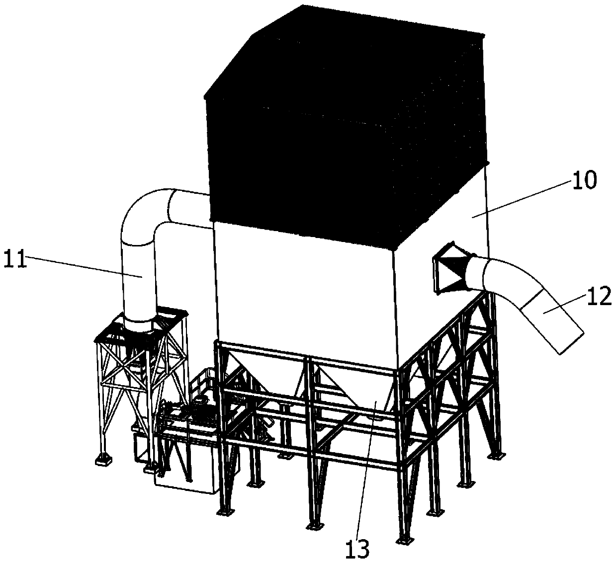
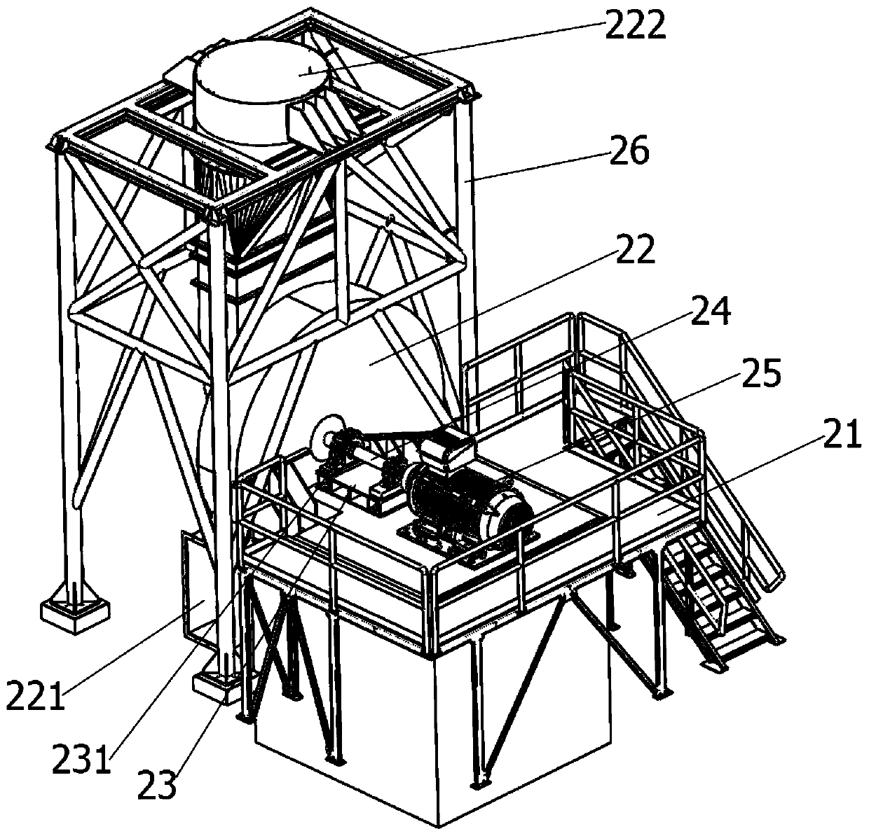
[0017] See Figure 1-2 As shown, the present invention provides a new type of dust removal equipment, including a dust collector 10 and an air intake unit.

[0018] The two sides of the dust collector 10 are respectively provided with an air inlet pipe 11 and an air exhaust pipe 12, and a purification component is arranged in the dust collector 10, and a discharge port 13 is arranged at the bottom of the dust collector 10, and the waste gas enters into the dust collector 10 through the air inlet pipe 11 to carry After the dust removal treatment, it is discharged from the exhaust pipe 12 to the outside.

[0019] The air intake unit includes a supporting platform 21 , an air intake fan 22 , a base 23 , a transmission rod 24 and a drive motor 25 . The air intake fan 22 includes an air inlet 221 and an air supply port 222, and the air s...


PUM


Abstract

The invention provides a novel dust removal device comprising a dust remover and a gas inlet unit. An air inlet pipe and an exhaust pipe are arranged on the two sides of the dust remover correspondingly. A purification assembly is arranged in the dust remover. Material discharge ports are arranged at the bottom of the dust remover. The gas inlet unit comprises a supporting table, a gas inlet draught fan, a base, a transmission rod and a drive motor. The gas inlet draught fan comprises an air inlet and an air sending port. The air sending port is connected with the air inlet pipe through a pipeline. The drive motor and the base are fixedly arranged on a supporting table. The output end of the drive motor is connected with the transmission rod. A rotation base is arranged on the base. The transmission rod is arranged in the rotation base in a penetrating manner. The end portion of the transmission rod is connected to the drive end of the gas inlet draught fan. An impeller in the gas inlet draught fan is driven to rotate through rotation of the transmission rod, and in this way, mold selection and replacement can be conveniently conducted on the drive motor on the supporting table andadjustment of the operation power of the gas inlet draught fan can be achieved through connection and assembly of the transmission rod so that dust removal treatment of large-flow waste gas can be achieved and operators can conveniently conduct replacement and adjustment.

Description

technical field [0001] The invention relates to the technical field of dust removal equipment, in particular to a novel dust removal equipment. Background technique [0002] In the process of production and processing, depending on the type of processing operations, a large amount of dust is usually generated on the production line, thereby reducing the processing environment of the production line and seriously affecting the processing quality. However, the suction efficiency of the existing dust removal equipment is low. If the suction is improved The wind efficiency needs to be adjusted to increase the power of the intake fan to meet the dust removal of a large amount of exhaust gas, which cannot be easily disassembled and replaced, which in turn reduces the dust removal efficiency and cannot meet the dust removal effect of a large amount of exhaust gas. Therefore, how to provide a dust removal device that can easily adjust the fan power to meet the dust removal treatment...

Claims


Application Information

Patent Timeline
Patent Type & Authority Applications(China)
IPC IPC(8): B08B15/04B01D49/00
CPCB01D49/00B08B15/04
Inventor 苏乃强
Owner 青岛铭宏智能装备科技有限公司
Learn More