To-be-detected device replacing device for valve strings and using method thereof

A technology of devices and valve strings, which is applied in the field of replacement devices for devices to be inspected, can solve the problems of large volume of press-fit modules, high risk factors, and damage to optical cables, and achieve the effects of good versatility, good safety, and light weight

Pending Publication Date: 2020-08-18
CHANGZHOU BORI ELECTRIC POWER AUTOMATION EQUIP +2
View PDF17 Cites 1 Cited by
  • Summary
  • Abstract
  • Description
  • Claims
  • Application Information

AI Technical Summary

Problems solved by technology

This type of press-fit module is large in size and heavy in weight. When the structural parts such as internal power devices or cooling plates fail, the module can only be disassembled for replacement. The operation is complicated, requiring large-scale mechanical assistance, high cost and high risk factor. , more likely to cause damage to vulnerable components such as optical cables

Method used


Image

  • To-be-detected device replacing device for valve strings and using method thereof
  • To-be-detected device replacing device for valve strings and using method thereof
  • To-be-detected device replacing device for valve strings and using method thereof

Examples


Embodiment 1

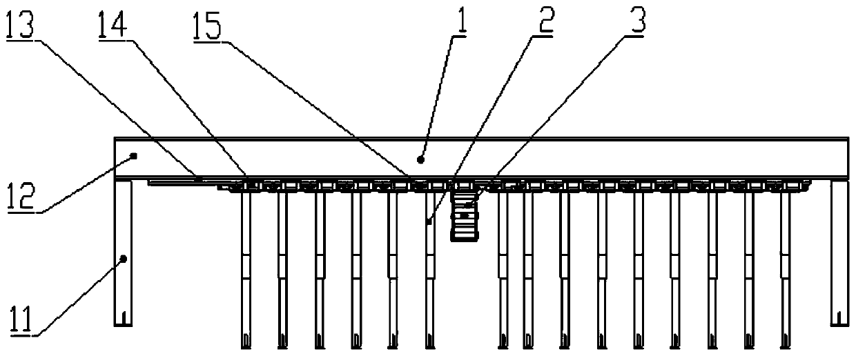
[0041] Such as Figure 1~4 As shown, a device to be tested for a valve string replacement device, which includes:

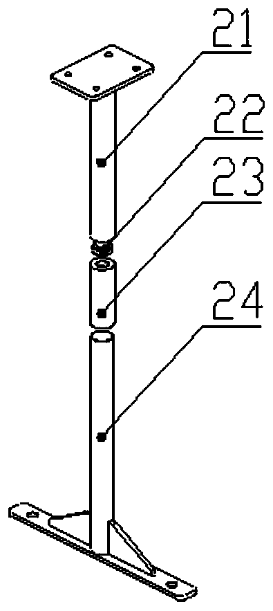
[0042] A support assembly 1, the support assembly 1 is suitable for being connected to the valve string 4;

[0043] At least one fixing component 2, the fixing component 2 is connected to the support component 1, and the fixing component 2 is suitable for fixing at least part of the remaining non-testing devices except the testing device;

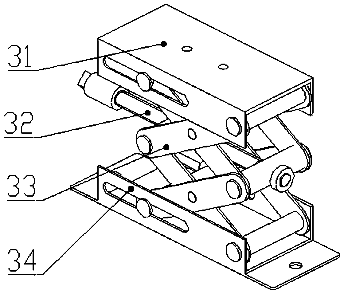
[0044] A lifting assembly 3, the lifting assembly 3 is connected to the support assembly 1, the lifting assembly 3 is suitable for connecting with the device to be inspected and driven to lift the device to be inspected.

[0045] In this embodiment, there are multiple fixing components 2, which are set correspondingly to the non-tested devices.

[0046] In this embodiment, both the device to be inspected and the device not to be inspected may refer to a heat sink.

[0047] Specifically, such as figure 1 As shown, the suppo...

Embodiment 2

[0072] A method for using the device for replacing the device to be inspected for the valve string in Embodiment 1, the steps of the method include:

[0073] Install the support assembly 1 on the valve string 4;

[0074] The fixing component 2 is connected and pressed against the corresponding non-tested device;

[0075] The lifting component 3 is connected to the device to be inspected, and the lifting component 3 is operated to lift the device to be inspected.

[0076] The concrete steps of the using method of the present embodiment are:

[0077] The first step, preparation work: the valve string 4 is powered off, and the control and protection device is removed;

[0078] The second step is to install the support assembly 1: use bolts to fix the support assembly 1 on the upper surface of the front and rear press-fit plates of the valve string 4 through the through holes of the support legs 11, and the upper surfaces of the press-fit plates are processed with corresponding ...


PUM


Abstract

The invention discloses a to-be-detected device replacing device for valve strings and a using method thereof. The to-be-detected device replacing device for the valve strings comprises a supporting assembly, at least one fixing assembly and a lifting assembly, and the supporting assembly is suitable for being connected to the valve strings; the fixing assemblies are connected to the supporting assembly, and the fixing assemblies are suitable for fixing at least part of other non-to-be-detected devices except the to-be-detected device; the lifting assembly is connected to the supporting assembly, and the lifting assembly is suitable for being connected with the to-be-detected device and is driven to lift the to-be-detected device. The to-be-detected device replacing device is convenient tobuild on the valve strings, devices in the device can be rapidly replaced, efficiency is high, and safety is good.

Description

technical field [0001] The invention relates to a replacement device for a device to be inspected for a valve string and a using method thereof. Background technique [0002] At present, in large-scale UHV power electronic equipment, such as converter valve towers and circuit breaker valve towers, most of the high-power devices such as IGBTs, diodes, and thyristors are stacked on specific pressure plates to form a large module. This type of press-fit module is large in size and heavy in weight. When the structural parts such as internal power devices or cooling plates fail, the module can only be disassembled for replacement. The operation is complicated, requiring large-scale mechanical assistance, high cost, and high risk factor. , more likely to cause damage to vulnerable components such as optical cables. Contents of the invention [0003] The technical problem to be solved by the present invention is to overcome the defects of the prior art and provide a replacement ...

Claims


Application Information

Patent Timeline
Patent Type & Authority Applications(China)
IPC IPC(8): B25B27/00
CPCB25B27/00
Inventor 陆凯雷曹杰刘贵黄莹瑛刘亮帅伟李夕晨孙旭
Owner CHANGZHOU BORI ELECTRIC POWER AUTOMATION EQUIP
Why Eureka
Try Eureka