Floating type underwater automatic charging pile

An automatic charging and floating technology, applied in electric vehicle charging technology, charging stations, underwater operation equipment, etc., can solve the problems of limited umbilical cable length, inability to return to the target location by itself, and exhaustion of power, so as to shorten the distance and time, improve the convenience of charging, and avoid the effect of power exhaustion

Pending Publication Date: 2020-08-18
海南电网有限责任公司
View PDF0 Cites 2 Cited by
  • Summary
  • Abstract
  • Description
  • Claims
  • Application Information

AI Technical Summary

Problems solved by technology

However, the marine environment is complex. During the recovery process of underwater unmanned equipment, the power will often be exhausted ahead of time and cannot return to the target location by itself, resulting in equipment loss.
When the underwater unmanned equipment uses the umbilical cable to obtain power from the mother ship, the range of movement of the equipment is limited due to the limited length of the umbilical cable
Also, the longer the umbilical, the greater the loss of power and the greater the risk of being severed

Method used


Image

  • Floating type underwater automatic charging pile
  • Floating type underwater automatic charging pile
  • Floating type underwater automatic charging pile

Examples


Embodiment 1

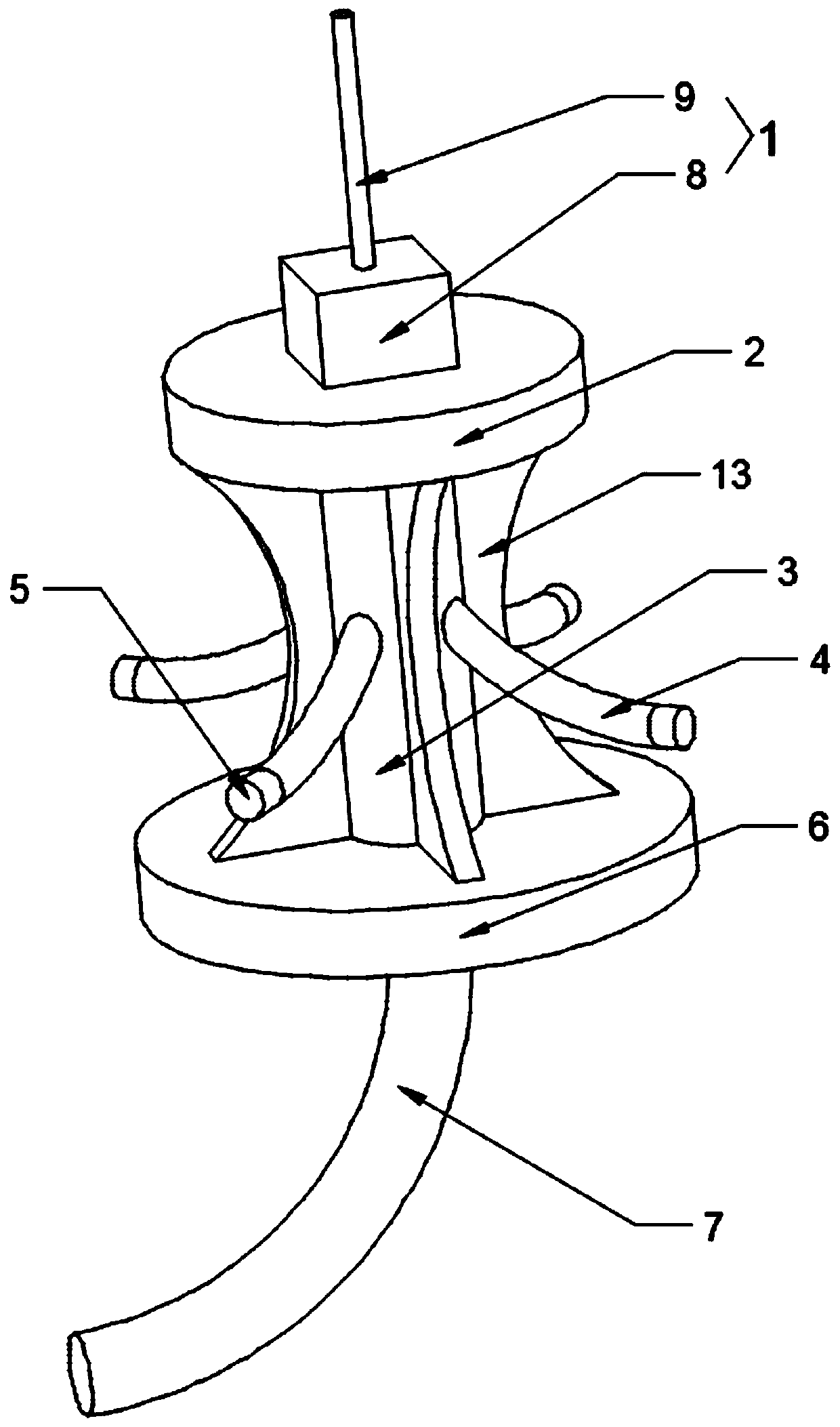
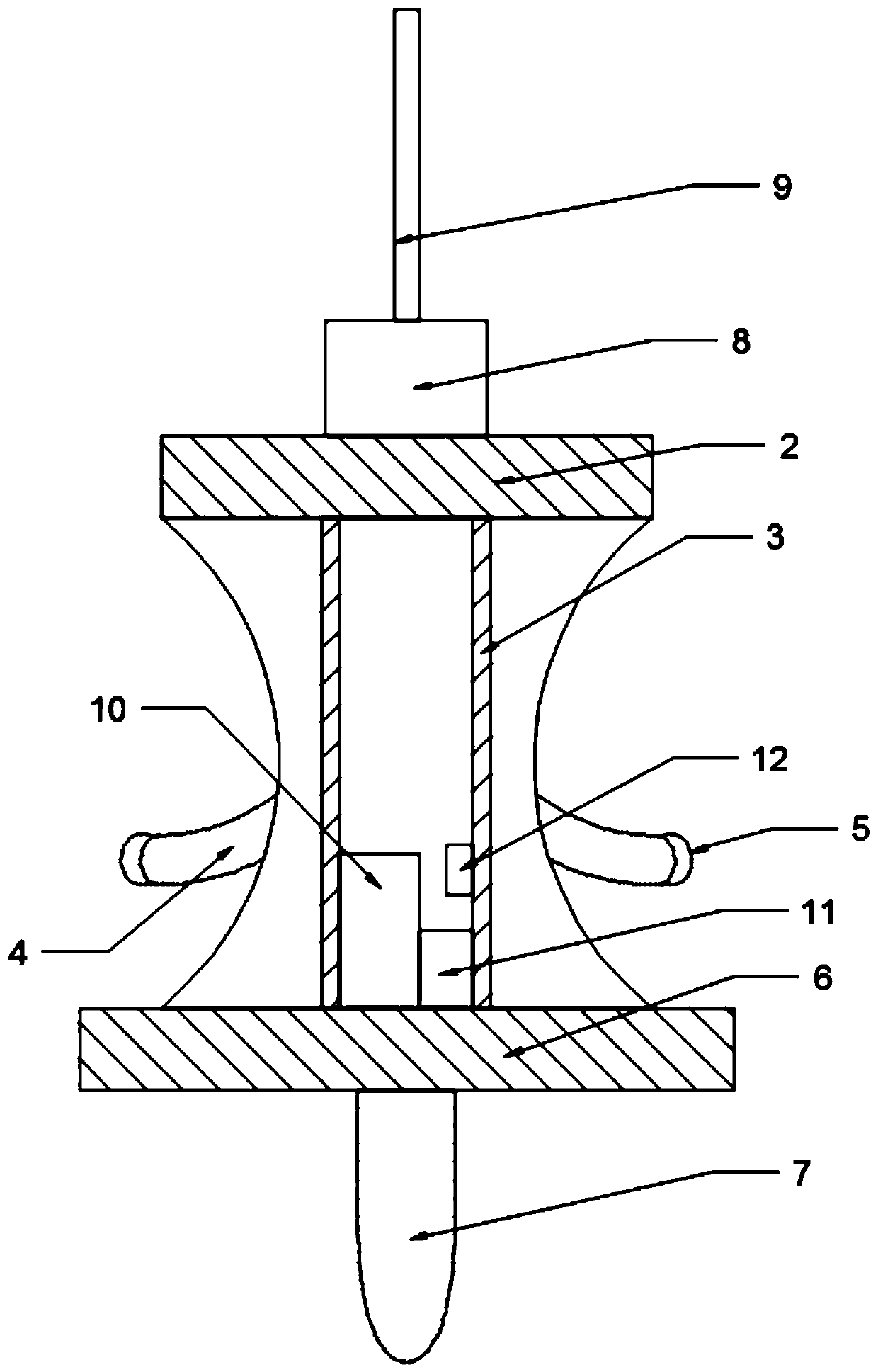
[0024] see Figure 1 to Figure 2 , the present invention provides a floating underwater automatic charging pile, including an information transmission tower 1, a water platform 2, a pile body 3, a charging cable 4, an underwater charging port 5, an underwater appendage 6, a main cable and an anchor chain 7 composition. The above-water platform 2 is floating on the water surface, the signal transmission tower is installed on the top of the above-water platform 2, the pile body 3 is connected to the bottom of the above-water platform 2, and the underwater appendage 6 is installed on the top of the above-water platform 2. The bottom of the pile body 3, the main cable is connected to the inside of the pile body 3, the charging cable 4 is distributed around the pile body 3, and the tail end of the charging cable 4 is connected to the inside of the pile body 3. The main cable is connected, the underwater charging port 5 is installed at the front end of the charging cable 4, the anc...

Embodiment 2

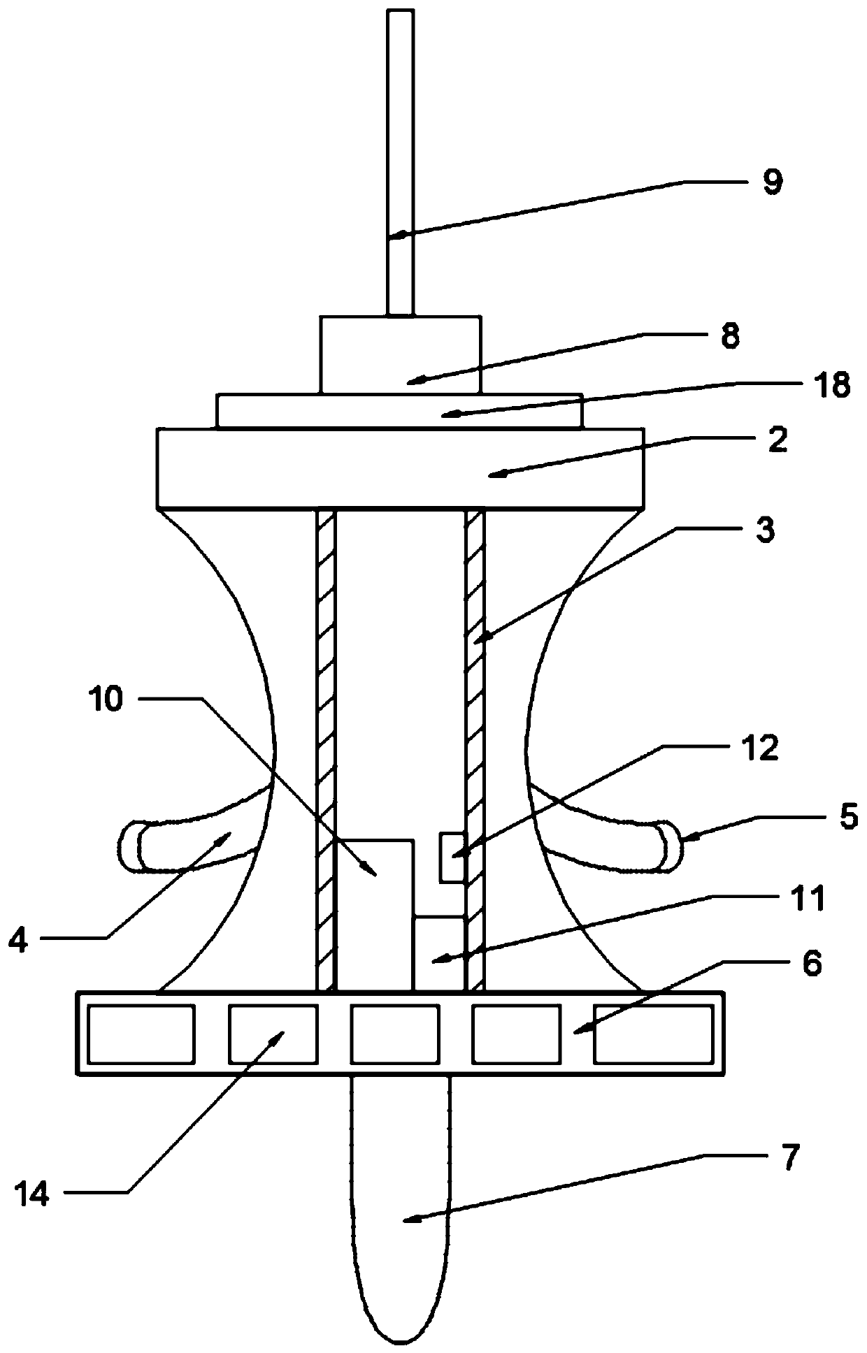
[0030] see Figure 3 to Figure 4 The difference between this embodiment and Embodiment 1 is that the interior of the underwater appendage 6 is divided into a plurality of independent compartments 14, and the underwater floating body 15 plays a balancing role for the device, and the plurality of independent compartments 14 inside Then provide buoyancy for this device.

[0031] The charging cable 4 is externally connected with a buoyancy component, and the gravity of the charging cable 4 and the underwater charging port 5 can be balanced by the buoyancy component to make them float in the water.

[0032] The buoyancy assembly includes a buoyancy body 15 and a gravity block 16, the gravity block 16 is connected to the bottom of the buoyancy body 15, the buoyancy body 15 plays a buoyancy role for the charging cable 4, by increasing or decreasing the number of gravity blocks 16, the buoyancy body 15 is changed The amount of buoyancy provided for the charging cable 4.

[0033] One...


PUM


Abstract

A floating type underwater automatic charging pile comprises an information launching tower, an overwater platform, a pile body, a charging cable, an underwater charging port, an underwater appendage,a main cable and an anchor chain. The overwater platform floats on water surface, the signal transmitting tower is mounted at the top of the overwater platform; the pile body is connected with the bottom of the water platform; the underwater appendage is installed at the bottom of the pile body, the main cable is connected with the interior of the pile body, the charging cables are distributed around the pile body, the tail ends of the charging cables are connected with the main cable in the pile body, the underwater charging port is installed at the front ends of the charging cables, the anchor chain is installed at the bottom of the underwater appendage, and automatic butt joint management is achieved through the charging pile and underwater unmanned equipment. Before charging, long-distance information interaction is carried out between the pile and the charging equipment, so that the path time of finding the charging pile by the unmanned equipment is greatly shortened, the unmanned equipment is prevented from running back to a target place due to electric energy exhaustion in the path finding process, the charging convenience of the unmanned equipment is greatly improved, andthe durability of the unmanned equipment is improved.

Description

technical field [0001] The invention relates to the technical field of charging piles, in particular to a floating underwater automatic charging pile. Background technique [0002] In ocean development, marine survey activities are becoming more and more frequent. Due to their limited power storage capacity, underwater unmanned equipment that has been working in the ocean for a long time either periodically recycles energy for energy supplementation, or relies on the mother ship to provide energy. However, the marine environment is complex. During the recovery process of underwater unmanned equipment, the power will often be exhausted ahead of time and cannot return to the target location by itself, resulting in equipment loss. When the underwater unmanned equipment uses the umbilical cable to obtain power from the mother ship, the range of movement of the equipment is limited due to the limited length of the umbilical cable. Also, the longer the umbilical, the greater the ...

Claims


Application Information

Patent Timeline
Patent Type & Authority Applications(China)
IPC IPC(8): B60L53/31B60L53/66B60L53/35B60L53/18B63C11/52
CPCB63C11/52B60L53/18B60L53/31B60L53/35B60L53/66Y02T10/70Y02T10/7072Y02T90/12Y02T90/14Y02T90/16
Inventor 吴清张广青郑耀东胡玉峰邢涛张小店黄立毅洪同庆
Owner 海南电网有限责任公司
Why Eureka
Try Eureka