
Composite joint with plate type rigidity adjusting structure

A compound joint and adjusting structure technology, which is applied in the direction of railway couplings, railway car body parts, traction devices, etc., can solve the problems of poor locomotive running stability, increase the stiffness of the coupler, lack of variable stiffness of the coupler, etc., and achieve slow down The effect of wear, low derailment coefficient and good dynamic requirements

Inactive Publication Date: 2020-08-18
ZHUZHOU TIMES RUIWEI ANTI VIBERATION EQUIP LTD
View PDF10 Cites 0 Cited by
  • Summary
  • Abstract
  • Description
  • Claims
  • Application Information

AI Technical Summary

Problems solved by technology

With the implementation of the railway speed-up and heavy-duty strategy, the number of failures affecting the running performance of the locomotive due to the lack of variable stiffness of the coupler and the fatigue damage of the rubber parts has gradually increased, and the stability of the locomotive has deteriorated, causing hidden dangers to driving safety.
[0003] Some of the current couplers are rigidly connected, and the cushioning performance is very poor
Some couplers also have a buffer structure, but the stiffness adjustment is relatively simple, lacking variable stiffness, and it is difficult to meet the vehicle's good buffer performance when starting with a small stiffness under heavy load; and it can produce variable stiffness during emergency braking or turning. Thereby greatly increasing the stiffness at the coupler to ensure the stability of the vehicle

Method used


Image

  • Composite joint with plate type rigidity adjusting structure
  • Composite joint with plate type rigidity adjusting structure
  • Composite joint with plate type rigidity adjusting structure

Examples


Embodiment 1

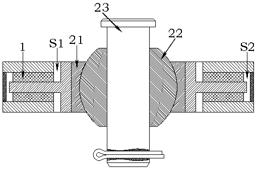
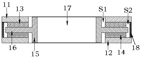
[0026] Such as figure 1 and image 3 As shown, the composite joint includes a rubber joint 1 and a metal joint, wherein the rubber joint 1 includes an end plate, a middle partition, a rubber body and an auxiliary ring 18 . And middle dividing plate comprises vertical dividing plate 15 and horizontal dividing plate 16, has the dividing plate through hole 17 that runs through vertical dividing plate 15 in the middle of vertical dividing plate 15, makes vertical dividing plate 15 be hollow circular tube shape. The transverse partition 16 is integrally formed on the outer side of the vertical partition 15, and the transverse partition 16 is in the shape of a hollow ring. When the middle partition is cut vertically, its section is two transverse and relatively distributed T-shaped sections.

[0027] An upper end plate 11 is arranged above the diaphragm 16, and an upper rubber body 13 is vulcanized between the diaphragm 16 and the upper end plate 11 to form a whole. A lower end p...

Embodiment 2

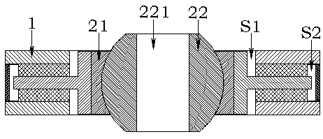
[0034] The difference from Embodiment 1 is that there is no auxiliary ring 18 in this embodiment, and when the intermediate partition moves in the radial direction relative to the end plates, the rubber body first deforms to provide linear stiffness. When the middle partition gradually moves to the end plate until the vertical partition 15 touches the end plate, the end plate will produce a damping force that prevents the middle partition from moving, and now the rubber joint 1 will become rigid. The cushioning performance of the composite joint in this embodiment in the radial direction will be worse than that of Example 1, but this embodiment can also be applied to working conditions where the vehicle does not require high cushioning performance but has high requirements for small-curvature turning of the vehicle .


PUM


Abstract

The invention relates to a composite joint with a plate type rigidity adjusting structure. The composite joint comprises a rubber joint and a metal joint, the rubber joint comprises an end plate, a middle partition plate and a rubber body, the middle partition plate and the end plate are vulcanized into a whole through the rubber body, a partition plate through hole penetrating through the middlepartition plate is formed in the middle partition plate, and the metal joint is installed in the partition plate through hole. A gap is formed between the inner wall of an auxiliary ring and a middleplate, a product provides small-rigidity performance before the gap disappears, and normal running of a vehicle is facilitated. When the vehicle starts to brake, the gap disappears, and large rigidityis provided. When the vehicle is hooked, the gap disappears, and impact load can be borne. In the vertical direction, large loads can be borne, the stability of the vehicle body can be kept, and theweight of the whole vehicle body is supported at extreme time. An up-and-down symmetrical structure is adopted, so that fluctuation of upper and lower loads of two-section marshalling of the product is facilitated.

Description

technical field [0001] The invention relates to a buffer device, in particular to a composite joint installed in a vehicle coupler. Background technique [0002] At present, in the manufacturing process of railway locomotives, couplers are widely used to connect two adjacent carriages. As a key component of the vehicle, the coupler has an important impact on the dynamic performance and running quality of the vehicle. With the implementation of the railway speed-up and heavy-duty strategy, the number of failures affecting the running performance of the locomotive due to the lack of variable stiffness due to the lack of variable stiffness of the coupler and the fatigue damage of the rubber parts gradually increased, and the stability of the running of the locomotive deteriorated, causing hidden dangers to driving safety. [0003] What present car coupler has is rigid connection, and cushioning performance is very poor. Some couplers also have a buffer structure, but the stiff...

Claims


Application Information

Patent Timeline
Patent Type & Authority Applications(China)
IPC IPC(8): B61G9/06B61G5/02
CPCB61G5/02B61G9/06
Inventor 许呈祥柳禄泱董永胡嘉亮相世举
Owner ZHUZHOU TIMES RUIWEI ANTI VIBERATION EQUIP LTD
Features
  • Generate Ideas
  • Intellectual Property
  • Life Sciences
  • Materials
  • Tech Scout
  • Unparalleled Data Quality
  • Higher Quality Content
  • 60% Fewer Hallucinations
Learn More