Fermentation tank with defoaming function

A fermentation tank and defoaming technology, applied in the field of fermentation, can solve the problems of contaminated bacteria, product loss, liquid escape, etc., and achieve the effect of improving the defoaming effect.

Inactive Publication Date: 2020-08-18
邹娜娜
View PDF0 Cites 3 Cited by
  • Summary
  • Abstract
  • Description
  • Claims
  • Application Information

AI Technical Summary

Problems solved by technology

[0003] However, when the fermenter is fermenting, a large amount of foam will often be formed in the tank. Excessive persistent foam will rise to the top of the tank and may seep out from the shaft seal, which will increase the chance of contaminating bacteria. If the control is not timely, it will cause Cause "fluid escape", resulting in loss of product

Method used


Image

  • Fermentation tank with defoaming function
  • Fermentation tank with defoaming function
  • Fermentation tank with defoaming function

Examples


Embodiment 1

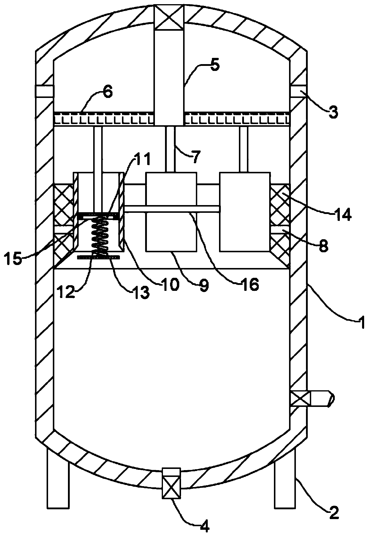
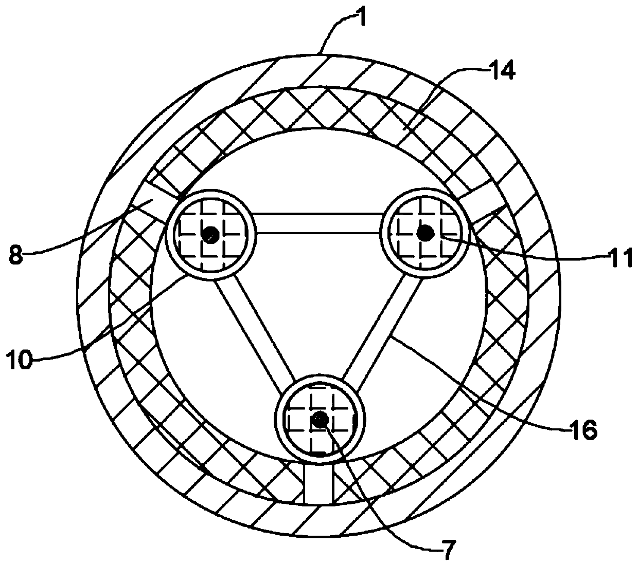
[0025] Such as Figure 1-3 As shown, a fermenter with defoaming function includes a tank body 1, a plurality of columns 2 are fixedly connected to the bottom of the tank body 1, the tank body 1 is supported by the columns 2, and the side wall of the tank body 1 is provided with an air outlet 3. The bottom of the tank body 1 is provided with a discharge port 4, and the top of the tank body 1 is fixedly connected with a feed channel 5. The feed channel 5 is opened and closed by a solenoid valve. In the closed state, it is airtight. There is a control panel 6 slidingly connected to the inner wall of the tank body 1 and the feed channel 5. The cross section of the control panel 6 is a circular structure. The inner wall of the tank body 1 is fixedly connected with a plurality of horizontally arranged fixed rods 8, and the other end of the fixed rods 8 is fixedly connected with a defoamer 9. The defoamer 9 includes a sleeve 10, and the sleeve 10 is provided with a The control rod 7...

Embodiment 2

[0033] Such as Figure 4-5 Shown, the difference between this embodiment and embodiment 1 is:

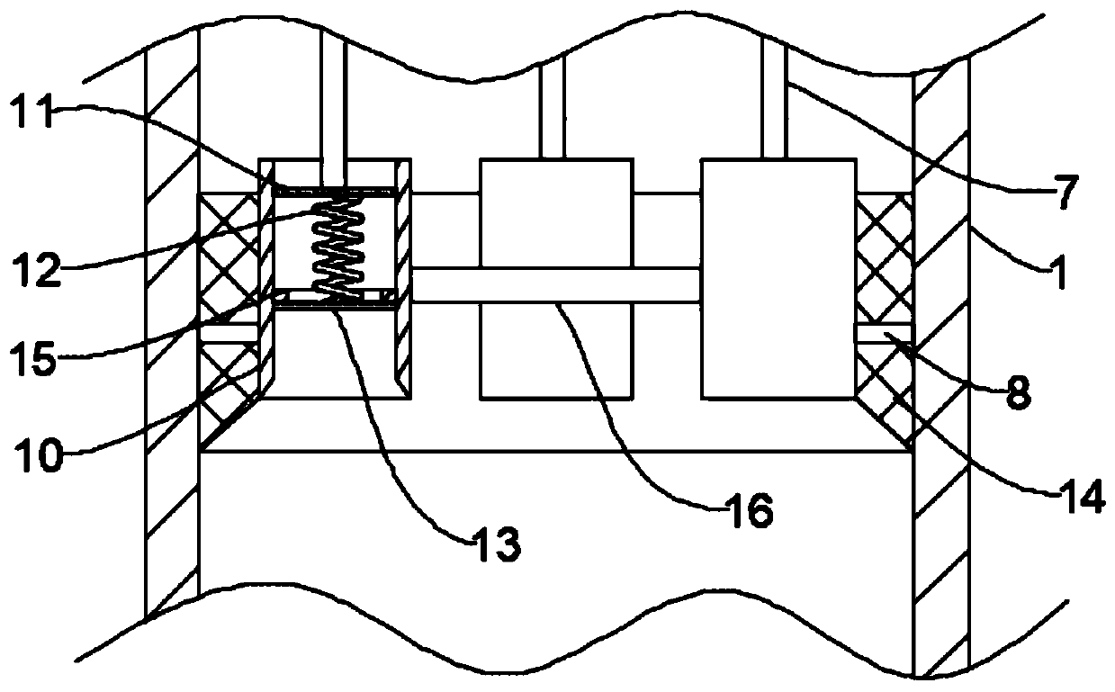
[0034]The side wall of the sleeve 10 is provided with an opening 17 connected to the bottom end of the filter screen 14, and the air bubbles will enter between the upper slide plate 11 and the lower slide plate 13 along the filter screen 14 from the opening 17, and then move upward on the control plate 6. The bottom of the sleeve 10 is fixedly connected with a defoaming plate 18. The defoaming plate 18 is provided with multiple groups of defoaming holes 19. The defoaming holes 19 are composed of channels that gradually become larger from top to bottom and communicate with each other. , during the upward movement of the control board 6, the control board 6 will drive the upper slide 11 to move upward through the control rod 7, and the upper slide 11 will drive the lower slide 13 to move upward through the spring 12, and the upward movement of the lower slide 13 will be in line with ...


PUM


Abstract

The invention belongs to the field of fermentation, in particular to a fermentation tank with a defoaming function. The fermentation tank comprises a tank body, and the bottom end of the tank body isfixedly connected with a plurality of upright posts. An air outlet is formed in the side wall of the tank body, and a discharge hole is formed in the bottom end of the tank body. The top end of the tank body is fixedly connected with a feeding channel. A control panel in sliding connection with the inner side wall of the tank body and the feeding channel is arranged in the tank body. The bottom end of the control panel is fixedly connected with a plurality of vertical control rods which are symmetrically arranged relative to the axis of the control panel. The inner wall of the tank body is fixedly connected with a plurality of horizontally-arranged fixing rods, the other ends of the fixing rods are fixedly connected with a defoamer, the defoamer comprises a sleeve, an upper sliding plate fixedly connected with the control rod is arranged in the sleeve, the bottom end of the upper sliding plate is fixedly connected with a spring, and the bottom end of the spring is fixedly connected with a lower sliding plate. By arranging the defoamer, the effect of reducing the air pressure in the defoamer to crush foam in the defoamer can be achieved when the air pressure in the tank body pushesthe control panel to move.

Description

technical field [0001] The invention belongs to the field of fermentation, in particular to a fermentation tank with defoaming function. Background technique [0002] Fermentation tanks are generally cylindrical in structure, and are mainly industrially used for microbial fermentation. Through the biological metabolism of microorganisms in the tank, metabolites are obtained, which can be used in dairy products, beverages, bioengineering, pharmaceuticals, Fine chemicals and other fields. [0003] However, when the fermenter is fermenting, a large amount of foam will often be formed in the tank. Excessive persistent foam will rise to the top of the tank and may seep out from the shaft seal, which will increase the chance of contaminating bacteria. If the control is not timely, it will cause Cause "fluid escape", resulting in loss of product. [0004] Therefore, we propose a fermenter with defoaming function to solve the above problems. Contents of the invention [0005] T...

Claims


Application Information

Patent Timeline
Patent Type & Authority Applications(China)
IPC IPC(8): C12M1/21C12M1/12C12M1/00
CPCC12M41/02
Inventor 邹娜娜耿协金
Owner 邹娜娜
Why Eureka
Try Eureka