Tai Chi type combustion system

A combustion system, Tai Chi technology, applied in the direction of burner, combustion method, combustion type, etc., can solve the problems of low combustion thermal efficiency, insufficient air ejection force, and small ejection space of the burner head, so as to increase the ejection channel. , Improve the ejection force, improve the effect of combustion heat efficiency

Pending Publication Date: 2020-08-18
ZHEJIANG SANFENG ELECTRONICS
View PDF0 Cites 0 Cited by
  • Summary
  • Abstract
  • Description
  • Claims
  • Application Information

AI Technical Summary

Problems solved by technology

[0002] Existing household gas stoves have the advantages of using upward-inlet burner burners, which can prevent tempering and extinguishing due to the opening and closing of cabinet doors, reduce the temperature of the glass panel and make explosion-proof, and the stoves are easy to clean. Due to traditional structural design reasons, the injection space of the furnace head is small, there are defects such as insufficient air injection force, and low combustion thermal efficiency.

Method used


Image

  • Tai Chi type combustion system
  • Tai Chi type combustion system
  • Tai Chi type combustion system

Examples


Embodiment 1

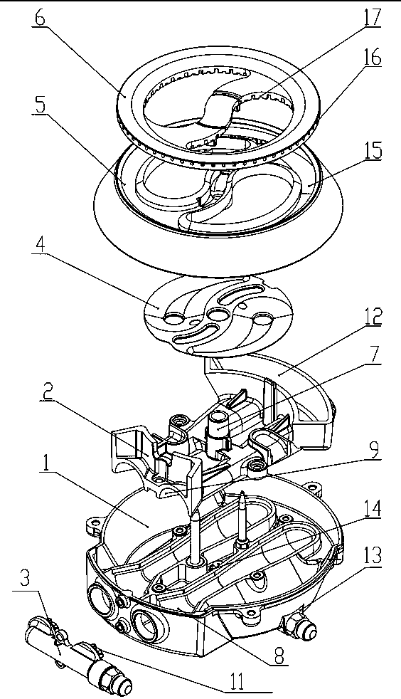
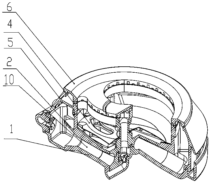
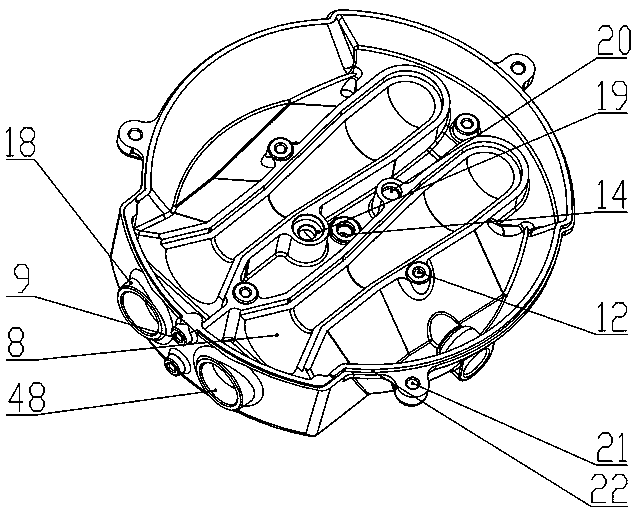
[0024] Example 1: Such as figure 1 and figure 2 As shown, the Tai Chi type combustion system includes the lower base of the furnace head 1, the upper base of the furnace head 2, the nozzle fixing base 3, the baffle plate 4, the fire cover base 5 and the fire cover 6. The lower base 1 of the furnace head is set in the most combustion system. The lower part is separately connected with the upper base 2 of the furnace head. The nozzle fixing base 3 is set on the side of the lower base 1 of the furnace head. In the middle of the upper base 2 of the furnace head is provided with a small fire ejection tube 7, a deflector 4 and 5 sets of fire cover bases. On the small fire ejection tube 7, the guide plate 4 is located between the upper base 2 of the furnace head and the flame cover base 5. The lower base 1 of the furnace is provided with the lower half 8 of the venturi ejection cavity, and the upper base of the furnace 2 There is the upper part 9 of the venturi ejection chamber, which...

Embodiment 2

[0025] Example 2: Such as Picture 11 As shown, in the Tai Chi type combustion system, the nozzle holder 3 is a pipe-shaped cylinder, one end of which is an air inlet 49, and two screw flanges 50 are provided in the middle to connect with the lower base of the burner 1, and the other One end is a gear-shaped positioning boss 51 communicating with the air inlet, and two nozzle installation ports 52 are provided in the center of the boss, and the rest are the same as in Embodiment 1.

Embodiment 3

[0026] Example 3: Such as Picture 12 As shown, in the Tai Chi type combustion system, the deflector 4 is a circular sheet formed by sheet metal stamping, the left and right sides are concave in the shape of Tai Chi, and the center of the Tai Chi on the left and right sides is provided with a deflector hole 53. Two ventilation slots 54, an ignition pin through hole 55, and a thermocouple through hole 34 are respectively provided in the middle, and the rest are the same as in Embodiment 1 or Embodiment 2.


PUM


Abstract

The invention discloses a Tai Chi type combustion system. The Tai Chi type combustion system comprises a burner lower base, a burner upper base, a nozzle fixing base, a flow guide disc, a burner cap base and a burner cap; a Venturi tube ejection cavity is formed between the burner lower base and the burner upper base, one side of the Venturi tube ejection cavity is provided with a strong fire nozzle fixed on the nozzle fixing base, and the other side of the Venturi tube ejection cavity is provided with a strong fire gas delivery port; a soft fire nozzle arranged on the burner lower base is located below a soft fire ejection tube and connected with a soft fire gas inlet channel; and the burner cap base and the burner cap are matched and each of a ring-shaped Tai Chi type through hole structure, and fire holes and fire teeth are distributed on the burner cap. The Tai Chi type combustion system has the advantages of being reasonable in structure, capable of reducing costs, high in combustion heat efficiency and the like.

Description

Technical field [0001] The invention relates to a burner, in particular to a burner for a gas stove. Background technique [0002] Existing household gas stoves have the advantages of preventing backfire extinguishing due to opening and closing of the cabinet door, lowering the temperature of the glass panel, and easy cleaning due to the use of the upper air inlet burner burner. However, most of the burners adopt the outer flame combustion structure. For reasons such as traditional structural design, the ejection space of the furnace head is small, and there are defects such as insufficient air ejection force and low combustion heat efficiency. Summary of the invention [0003] The purpose of the present invention is to provide a Tai Chi type combustion system with reasonable structure, cost saving and high combustion heat efficiency. [0004] To achieve the above objective, the present invention is achieved through the following technical solutions. Tai Chi combustion system, inc...

Claims


Application Information

Patent Timeline
Patent Type & Authority Applications(China)
IPC IPC(8): F23D14/26F23D14/46F23D14/58
CPCF23D14/26F23D14/46F23D14/58F23D2900/14003
Inventor 陈观峰王建伟王永伟詹骁驰
Owner ZHEJIANG SANFENG ELECTRONICS
Why Eureka
Try Eureka