Self-lubricating gear with oil supply and return functions and sealing assembly

A self-lubricating, gear technology, applied to components with teeth, gear lubrication/cooling, belts/chains/gears, etc., can solve the accuracy and life hazards of gear transmission systems, increase gear oil churning resistance, and mesh tooth surfaces Lack of oil lubrication and other problems, to achieve the effect of good oil leakage prevention, enhanced ejection power, and meet the work requirements

Active Publication Date: 2021-06-01
ANHUI UNIVERSITY OF TECHNOLOGY +1
View PDF13 Cites 0 Cited by
  • Summary
  • Abstract
  • Description
  • Claims
  • Application Information

AI Technical Summary

Problems solved by technology

[0003] Most of the existing gear transmission devices adopt the splash lubrication method, that is, the rotating gears bring the oil at the bottom of the gear box into the gear mesh for lubrication, but the amount of lubricating oil for splash lubrication is not easy to control: it is difficult to achieve effective lubrication when the amount of lubricating oil is small. Lubrication; when the amount of lubricating oil is large, the oil churning resistance of the gear is increased, and the transmission efficiency and oil temperature rise are large, which affects the lubrication quality
In addition, when the lubricating oil is exhausted, if the lubricating oil is not replenished in time, it will lead to abnormal wear of the tooth surface. Therefore, frequent refueling and maintenance are required, which increases labor costs and brings great hidden dangers to equipment operation and production safety.
[0004] With the development of gear transmission towards high speed and heavy load, the huge centrifugal force when the gear rotates at high speed makes it difficult for the lubricating oil to adhere to the gear, and the amount of lubricating oil entering the meshing area is small, resulting in insufficient lubrication, and the high contact load also makes The oil is squeezed out of the meshing area, making it difficult to form an effective dynamic pressure oil film, and the meshing tooth surface is prone to lack of oil lubrication, which will seriously damage the accuracy and life of the gear transmission system

Method used


Image

  • Self-lubricating gear with oil supply and return functions and sealing assembly
  • Self-lubricating gear with oil supply and return functions and sealing assembly
  • Self-lubricating gear with oil supply and return functions and sealing assembly

Examples


Embodiment 1

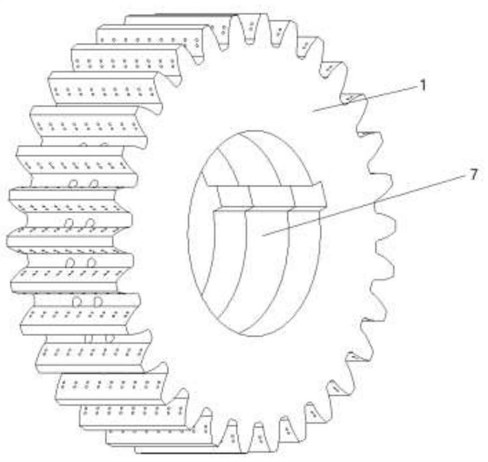
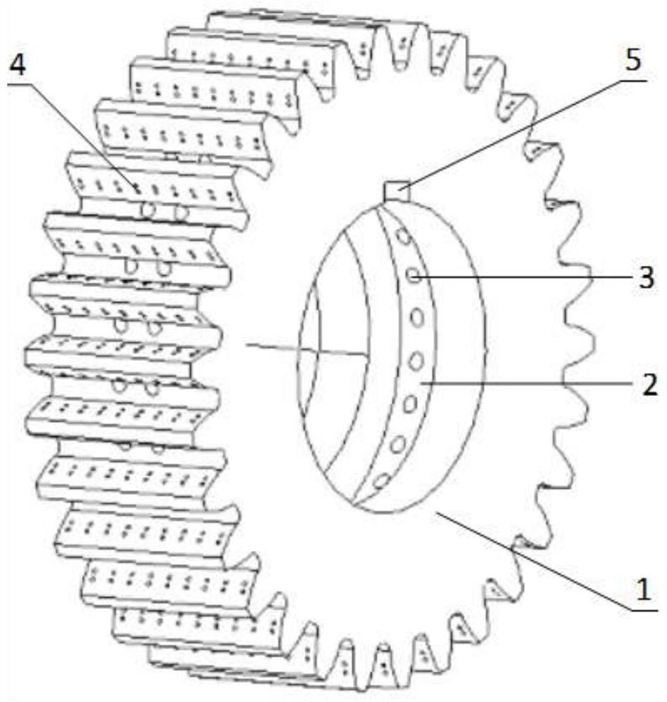
[0027] from figure 1 , figure 2 , image 3 , Figure 4 It can be seen that a self-lubricating gear with oil supply and oil return function of the present invention comprises a gear base 1, an oil storage groove 2, a porous oil storage body 7, an oil hole 3, a tooth surface micro-texture 4, and a keyway 5; The oil groove 2 is ring-shaped as a whole, set in the inner hole of the gear base 1, and extends to the inside of the gear base 1; the porous oil storage body 7 is ring-shaped as a whole, and is installed in the oil storage groove 2; the oil hole 3 is opened at one end On the top of the oil storage groove 2, the other end is set on the dedendum circle at the tooth groove of the gear base 1; the tooth surface micro-texture 4 is set on the front and rear tooth surfaces of each tooth of the gear base 1, The tooth surface micro-texture 4 is a cylindrical pit.

[0028] Wherein, the outer ring surface of the oil storage groove 2 is aligned with the inner hole of the gear, and...

Embodiment 2

[0031] Self-lubricating gear of the present invention: the material of porous oil storage body 7 is by one or more combinations in polyimide (PI), polyethyleneimine (PEI) etc.; Porous oil storage body 7 is based on cold press sintering Manufactured by technology, the pressing pressure is 200MPa-300MPa, the sintering temperature is 250°C-300°C, the holding time is 2h, and the oil storage rate of the sintered porous oil storage body is 45%-68%.

[0032] Polyimide (PI) and polyethyleneimine (PEI) are organic polymer materials, which have good stability and can still have good performance under high temperature conditions. The porous oil storage body 7 is made based on the cold press sintering process. After cold press sintering and vacuum oil immersion treatment, the porous oil storage body has a certain pore oil content and also has a certain mechanical strength. The pores inside the porous oil storage body 7 are randomly distributed, and the pores have a strong ability to lock ...

Embodiment 3

[0034] The self-lubricating gear of the present invention: the porous oil storage body 7 has a ring structure as a whole, and a keyway is arranged at the connection position of the flat key, which is matched and installed in the oil storage groove 2 .

[0035] The porous oil storage body 7 is installed in the oil storage groove 2, the two are in interference fit, and the keyway on it and the keyway on the gear base 1 form a whole, which is easy to install the flat key.


PUM

PropertyMeasurementUnit
Diameteraaaaaaaaaa
Diameteraaaaaaaaaa
Depthaaaaaaaaaa

Abstract

The invention discloses a self-lubricating gear with oil supply and return functions. The self-lubricating gear comprises a gear base body, an oil storage groove, a porous oil storage body, an oil hole, tooth surface microstructures and key grooves; the whole oil storage groove is annular, is formed in an inner hole of the gear base body and extends into the gear base body; the whole porous oil storage body is annular and is mounted in the oil storage groove in a matched manner; one end of the oil hole is formed in the top of the oil storage groove, and the other end is formed in a tooth root circle of a gear tooth groove of the gear base body; the tooth surface microstructures are formed in the front tooth surface and the rear tooth surface of each gear tooth of the gear base body, and the tooth surface microstructures are cylindrical pits. According to the self-lubricating gear, lubricating oil can be supplied to the gear tooth meshing part, dynamic pressure oil film lubrication is formed on the tooth surface, and after the gear stops rotating, oil liquid permeates back and is stored again so as to be recycled.

Description

technical field [0001] The invention relates to the technical field of gear transmission, in particular to a self-lubricating gear with the function of spontaneous oil supply and oil return. Background technique [0002] Gear transmission has the advantages of simple structure, large transmission torque, high working efficiency, and wide applicable speed range. It is widely used in mechanical equipment such as couplings, gearboxes, and reducers. After working for a certain period of time, there are many forms of gear failure and damage, such as tooth surface wear, gluing, tooth root fracture, etc. The occurrence of these phenomena is mostly related to early failure of gears caused by improper lubrication. How to achieve efficient lubrication of gear transmission is an urgent problem to be solved in the industry. [0003] Most of the existing gear transmission devices adopt the splash lubrication method, that is, the rotating gears bring the oil at the bottom of the gear box...

Claims


Application Information

Patent Timeline
IPC IPC(8): F16H55/17F16H57/04F16H57/00
CPCF16H55/17F16H57/0431F16H57/0456F16H57/00
Inventor 张国涛张志伟王孝义夏清华杨晓红朱长江李天超
Owner ANHUI UNIVERSITY OF TECHNOLOGY
Why Eureka
Try Eureka