heating cooker

A cooker and heater technology, which is applied in the direction of heating methods, electric heating fuel, lighting and heating equipment, etc., can solve the problems of longer cooking time, achieve uniform color, shorten cooking time, and shorten heating and cooking time.

Inactive Publication Date: 2016-01-20
SHARP KK
View PDF7 Cites 0 Cited by
  • Summary
  • Abstract
  • Description
  • Claims
  • Application Information

AI Technical Summary

Problems solved by technology

Therefore, although the temperature distribution in the above-mentioned space is uniform, the temperature of the air that becomes hot air after exchanging heat with the above-mentioned heater drops before reaching the holes of the above-mentioned perforated plate, so there is also a problem that the cooking time becomes longer.

Method used


Image

  • heating cooker
  • heating cooker
  • heating cooker

Examples


Embodiment Construction

[0071] Hereinafter, the present invention will be described in detail using the illustrated embodiments.

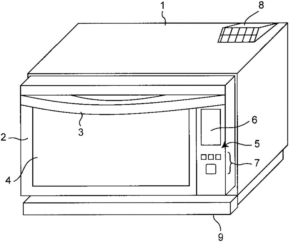
[0072] figure 1 It is a front perspective view of the heating cooker of this embodiment. The above-mentioned heating cooker is provided with a door 2 on the front surface of a rectangular parallelepiped casing 1, and the door 2 rotates substantially around the lower end side. The handle 3 is attached to the upper part of the said door 2, and the heat-resistant glass 4 is attached to the substantially center on the other hand. In addition, an operation panel 5 is provided on the right side of the door 2 in the figure. The operation panel 5 has a color liquid crystal display unit 6 and a button group 7 . In addition, an exhaust duct 8 is provided on the upper right rear side of the casing 1 . In addition, a dew-receiving container 9 is installed under the door 2 of the casing 1 .

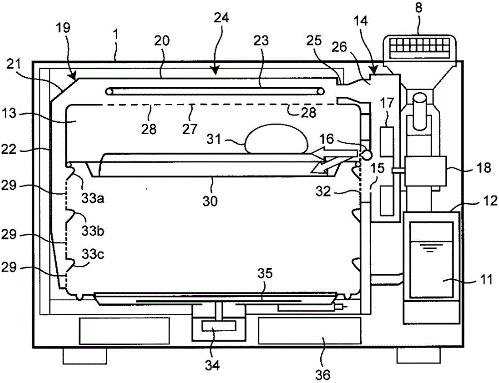
[0073] figure 2 From figure 1 A longitudinal sectional schematic view of the shown he...


PUM


Abstract

A partitioning part (37a) for guiding the flow of saturated water vapor, that was sprayed from a connection tube (25d), towards a superheated steam producing heater (23) by being bent upward at an angle of approximately 45° is disposed on the upstream side of a partitioning plate (37) for partitioning the interior of a first duct part (20) into an upper portion and a lower portion. As a consequence, the heat exchange efficiency of the saturated water vapor and the superheated steam producing heater (23) at the upstream side of the first duct part (20) where the flow rate of the saturate water vapor is fast is improved by forcibly passing the saturated water vapor that was just vigorously blown into the first duct part (20) through the section of the superheated steam producing heater (23). Thus, it is possible to equalize the manner by which an object to be heated changes color at the downstream side and upstream side of the flow of the saturated water vapor, and as a result it is possible to shorten the cooking time.

Description

technical field [0001] The present invention relates to a heating cooker for heating an object to be heated by supplying a heat medium heated in a chamber provided along the top surface of the heating cooking chamber into the heating cooking chamber. Background technique [0002] Conventionally, as a heating cooker, there exists a heating cooker disclosed in Unexamined-Japanese-Patent No. 2009-281637 (patent document 1). [0003] In the above-mentioned conventional heating cooker, air is supplied from a blower (fan) arranged behind the heater chamber to the heater chamber arranged on the upper part of the cooking chamber for heating, and the obtained hot air is sent from a A plurality of wells on the perforated plate provide access to the cooking chamber. Thus, the cooking items in the cooking chamber are heated by the hot air supplied into the cooking chamber. [0004] However, the above-mentioned conventional heating cooker has the following problems. [0005] That is, ...

Claims


Application Information

Patent Timeline
Patent Type & Authority Patents(China)
IPC IPC(8): F24C1/00
CPCF24C15/325F24C7/06H05B6/6411H05B6/6485
Inventor 峯冈竜也西岛正浩上田真也
Owner SHARP KK
Why Eureka
Try Eureka