
Method for predicting temperature of circulating liquid of medium-deep U-shaped heat exchange well

A prediction method and circulating fluid technology, applied in the application of thermometers, geothermal energy prediction/simulation, temperature measurement of moving fluids, etc., can solve the problem of large equipment investment, inability to predict the temperature change trend of circulating fluid, and inconvenient arrangement of temperature monitoring components and other issues to achieve the effect of reducing equipment investment

Active Publication Date: 2020-08-18
SHANDONG JIANZHU UNIV
View PDF5 Cites 3 Cited by
  • Summary
  • Abstract
  • Description
  • Claims
  • Application Information

AI Technical Summary

Problems solved by technology

[0006] The inventors found that for the monitoring of the temperature of the circulating fluid in mid-deep U-shaped wells, a large number of temperature monitoring elements need to be arranged in mid-deep U-shaped wells. Since the mid-deep U-shaped wells are buried deep, the arrangement of temperature monitoring elements is inconvenient. Moreover, the number of temperature monitoring components required is large, the equipment investment is large, and it is impossible to predict the temperature change trend of the circulating fluid, especially the temperature change after one year or even several years, and it is difficult to obtain data through experiments.

Method used


Image

  • Method for predicting temperature of circulating liquid of medium-deep U-shaped heat exchange well
  • Method for predicting temperature of circulating liquid of medium-deep U-shaped heat exchange well
  • Method for predicting temperature of circulating liquid of medium-deep U-shaped heat exchange well

Examples


Embodiment Construction

[0016] It should be pointed out that the following detailed description is exemplary and intended to provide further explanation to the present application. Unless defined otherwise, all technical and scientific terms used herein have the same meaning as commonly understood by one of ordinary skill in the art to which this application belongs.

[0017] It should be noted that the terminology used here is only for describing specific implementations, and is not intended to limit the exemplary implementations according to the present application. As used herein, unless the context clearly dictates otherwise, the singular is intended to include the plural, and it should also be understood that when the terms "comprising" and / or "comprising" are used in this specification, they mean There are features, steps, operations, means, components and / or combinations thereof.

[0018] For the convenience of description, if the words "up", "down", "left" and "right" appear in the present i...


PUM

PropertyMeasurementUnit
depthaaaaaaaaaa

Abstract

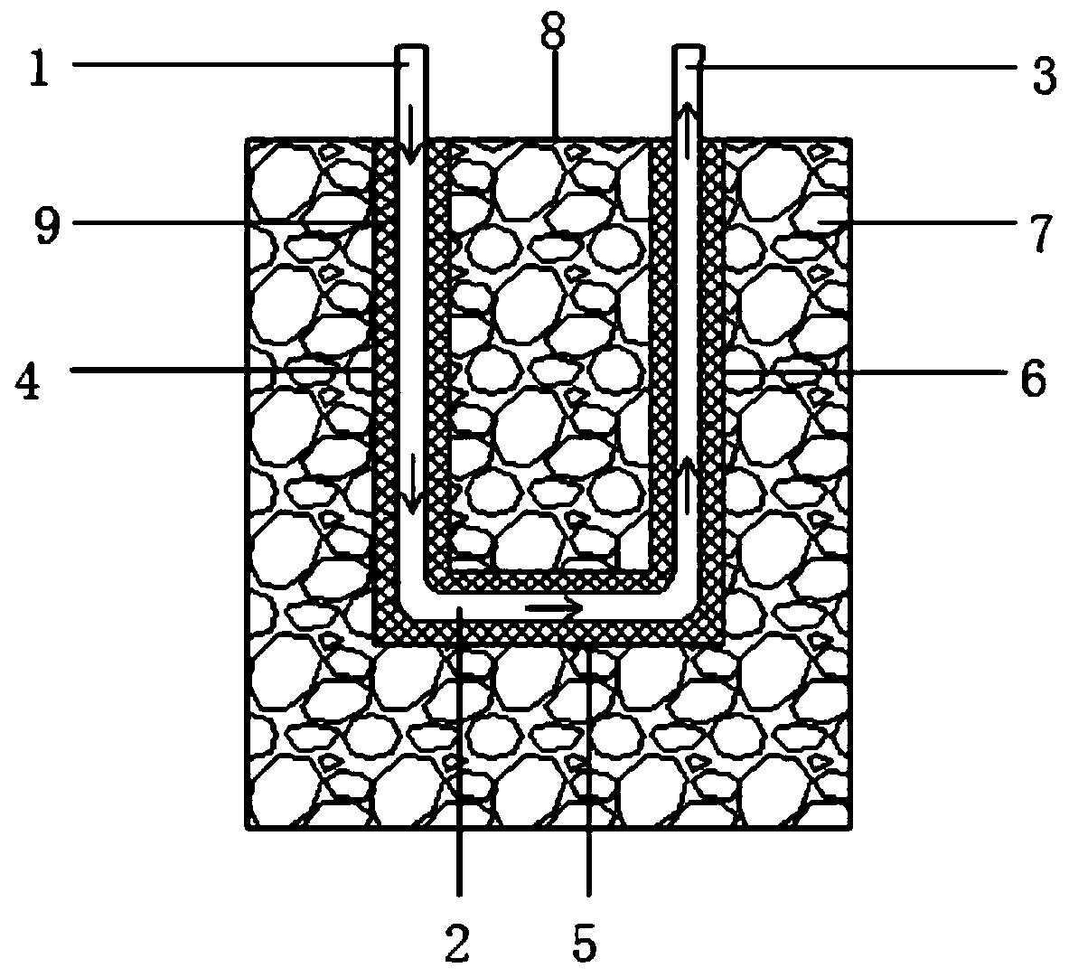
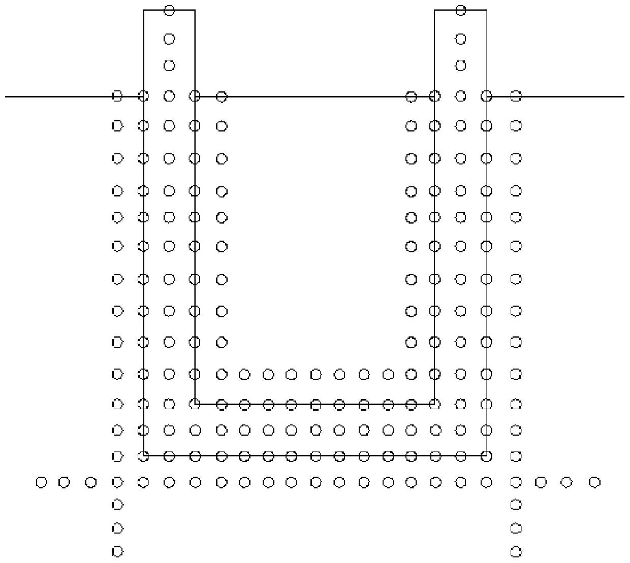
The invention relates to a method for predicting the temperature of the circulating liquid of a medium-deep U-shaped heat exchange well. The medium-deep layer U-shaped heat exchange well comprises a descending pipe, a horizontal pipe and an ascending pipe. A plurality of nodes are arranged in the medium-deep layer U-shaped heat exchange well and rock soil on the periphery of the medium-deep layerU-shaped heat exchange well. And temperature information of the nodes at the circulating liquid inlet and the peripheral rock and soil nodes at the circulating liquid inlet at the initial moment is collected, the collected temperature information is substituted into a prediction model formed by node equations of the multiple nodes in the medium-deep layer U-shaped heat exchange well, and temperature information of other position nodes and other moments of the medium-deep layer U-shaped heat exchange well is obtained. The method is low in equipment investment, and the change rule of the temperature of the circulating liquid along with the position and time can be mastered.

Description

technical field [0001] The invention relates to the technical field of construction environment and energy application engineering, in particular to a method for predicting the temperature of circulating fluid in a U-shaped heat exchange well in a middle-deep layer. Background technique [0002] The statements herein merely provide background information related to the present invention and do not necessarily constitute prior art. [0003] Ground source heat pump technology is popularized and applied due to its advantages in energy saving and environmental protection. The underground medium provides cooling and heat to buildings in summer and winter respectively. The whole system is composed of buried tube heat exchanger, heat pump unit and indoor terminal equipment, while the buried tube heat exchanger reflects the difference between ground source heat pump and other types of heat pump. In recent years, the shallow geothermal energy in the range of 50m to 200m from the gro...

Claims


Application Information

Patent Timeline
Patent Type & Authority Applications(China)
IPC IPC(8): G01K13/02G01K3/14G01K3/10F24T10/15
CPCG01K13/02G01K3/10G01K3/14F24T10/15F24T2201/00G01K13/026Y02E10/10
Inventor 张文科关春敏孙炳岩王建华
Owner SHANDONG JIANZHU UNIV
Learn More