Spiral rotor modeling method based on virtual generating machining

A modeling method and rotor technology, applied in 3D modeling, image data processing, special data processing applications, etc., can solve the problems of product quality, hidden dangers, complex analytical equations, etc., to meet the requirements of sealing and ensure reliability sexual effect

Active Publication Date: 2020-08-18
HEFEI UNIV
View PDF3 Cites 1 Cited by
  • Summary
  • Abstract
  • Description
  • Claims
  • Application Information

AI Technical Summary

Problems solved by technology

[0005]1. The analytical equation derived and established by solving the end surface profile curve of the helical rotor is relatively complicated, and it is not easy to apply in actual generation;
[0006]2. For the constructed helical rotor model, it is difficult to visually verify the correctness of the meshing of the gear teeth; therefore, there are quality risks in the subsequent processed products;

Method used


Image

  • Spiral rotor modeling method based on virtual generating machining
  • Spiral rotor modeling method based on virtual generating machining
  • Spiral rotor modeling method based on virtual generating machining

Examples


Embodiment 1

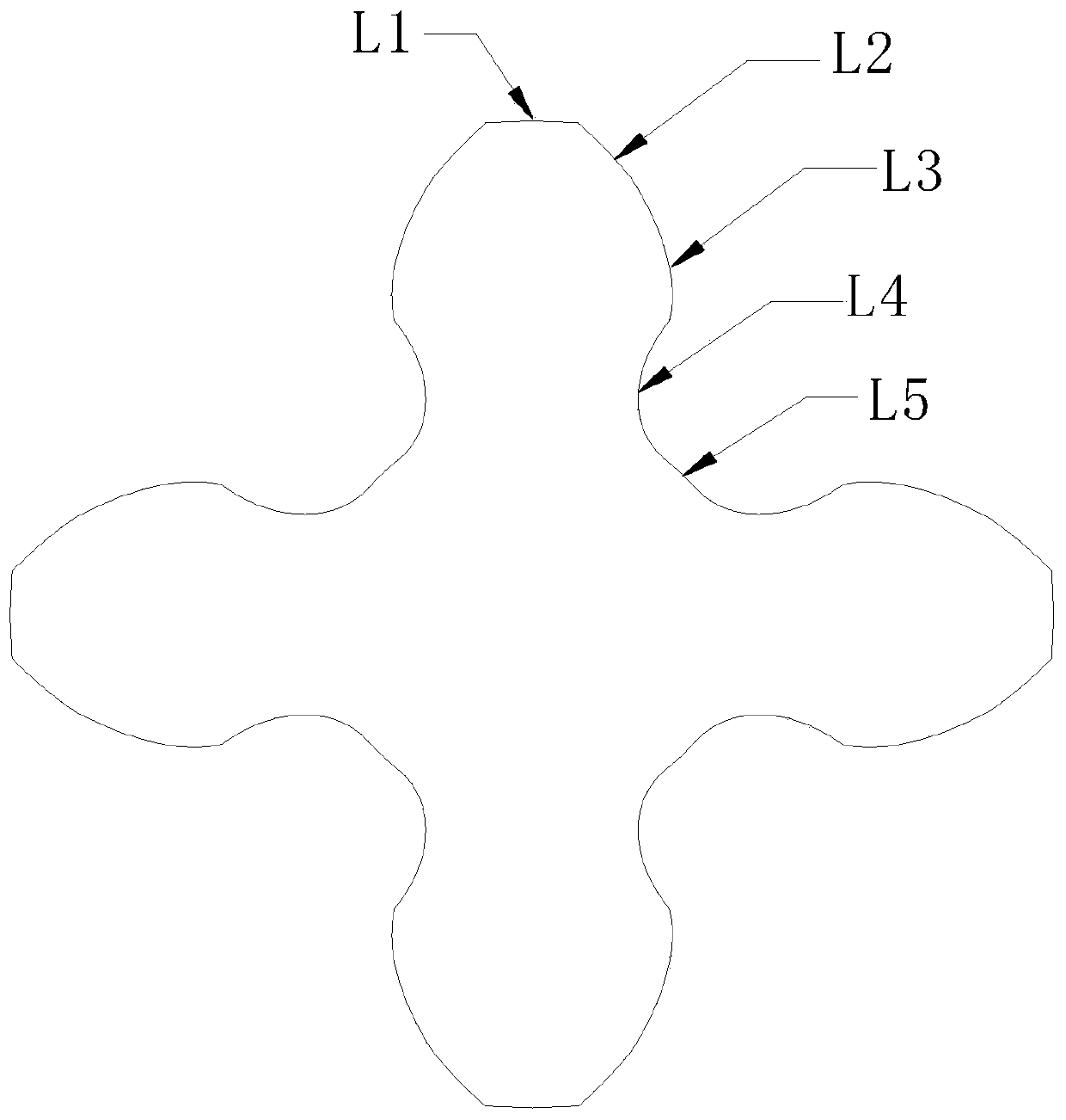
[0050] A helical rotor modeling method based on virtual fan-forming machining. Before modeling, it is necessary to determine the end surface profile of the helical rotor, such as figure 1 As shown, the compound tooth shape of the end face of the helical rotor includes the addendum arc segment L1, the transition curve II segment L2, the involute segment L3, the transition curve I segment L4, and the dedendum arc segment L5.

[0051] The modeling method of the helical rotor includes the following steps:

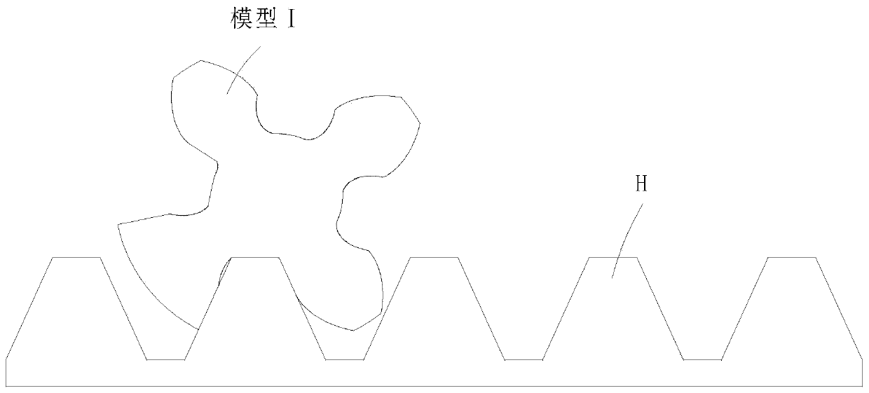
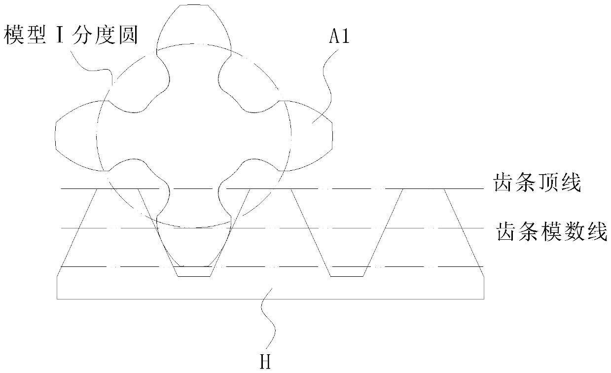
[0052] Step 1, such as figure 2As shown in Fig. 1, a suitable rack-shaped tool H is constructed by two-dimensional software, and the circular rotor blank model Ⅰ is processed by using the rack-shaped tool H to simulate the formation process of the tooth surface opening line, and the preliminary rotor end face A1 is obtained;

[0053] In this embodiment, the two-dimensional software is a computer-aided drawing program AutoCAD and an auxiliary assignment program developed by Au...

Embodiment 2

[0097] The difference between this embodiment and embodiment 1 is that, as Figure 12 As shown, in order to visually verify the correctness of the meshing of the modified rotor end face A4 profile model obtained by the above software, and the correctness of the modeling method of the end face profile of the helical rotor obtained through the above theoretical analysis and the correctness of the programming software running results, after the fourth step , using the above modified rotor end face A4 as the verification rotor tool O3, the circular rotor blank model IV is virtualized and processed, and the tooth surface opening line formation process is simulated to obtain the calibrated rotor end face A5, and the corrected rotor end face A4 and the calibrated rotor end face A5 are Perform coincidence comparison, verify the shape of the contour curves of the two, and go to step five after verifying that they are consistent.

[0098] After inspection, it is found that the contour c...


PUM


Abstract

The invention relates to the technical field of spiral rotor flow meters, and provides a spiral rotor modeling method based on virtual generating machining. The method aims to solve the problem that atraditional spiral rotor modeling method depends on the meshing principle, an end face profile curve analytical equation is established through derivation to obtain an end face profile curve of the spiral rotor, and a three-dimensional solid model generated on the basis has multiple defects. The method comprises the following steps of 1, constructing a rack-type cutter through two-dimensional software, carrying out virtual generating processing on a circular rotor blank model I by using the rack-type cutter, and simulating a tooth surface open line forming process to obtain a preliminary rotor end surface, and 2, taking the preliminary rotor end surface as a preliminary rotor cutter, carrying out virtual generating processing on the circular rotor blank model II, and simulating a tooth surface open line forming process to obtain a secondary rotor end surface. The method is particularly suitable for efficient and accurate modeling of the spiral rotor, and has high social use value andapplication prospect.

Description

technical field [0001] The invention relates to the technical field of helical rotor flowmeters, in particular to a modeling method for helical rotors based on virtual modeling. Background technique [0002] The helical rotameter is an advanced positive displacement flowmeter, which has the advantages of simple and exquisite structure, stable liquid flow, uniform torque, low noise, good repeatability, and high precision. It is widely used in various fields such as petroleum and chemical industry; in my country It is being gradually promoted and applied, and has considerable market potential. [0003] The core component of the helical rotameter is a pair of intermeshing helical rotors, whose structural shape will directly affect the working performance of the flowmeter. The two rotors in the helical rotameter rotate smoothly without interference, and must first meet the basic law of tooth profile meshing, that is, the working tooth surfaces of the two rotors should be a pair ...

Claims


Application Information

Patent Timeline
Patent Type & Authority Applications(China)
IPC IPC(8): G06F30/17G06T17/10
CPCG06F30/17G06T17/10
Inventor 姜海田春艳汪成陈超超张林
Owner HEFEI UNIV
Why Eureka
Try Eureka