Cashew nut shell opening device
A technology of cashew nuts and suits, which is applied in the fields of shelling, pod removal, and food science. It can solve the problems of easy fatigue, low work efficiency, and easy injury of human hands by tools, so as to avoid hand injury and work high efficiency effect
- Summary
- Abstract
- Description
- Claims
- Application Information
AI Technical Summary
Problems solved by technology
Method used
Image
Examples
Embodiment 1
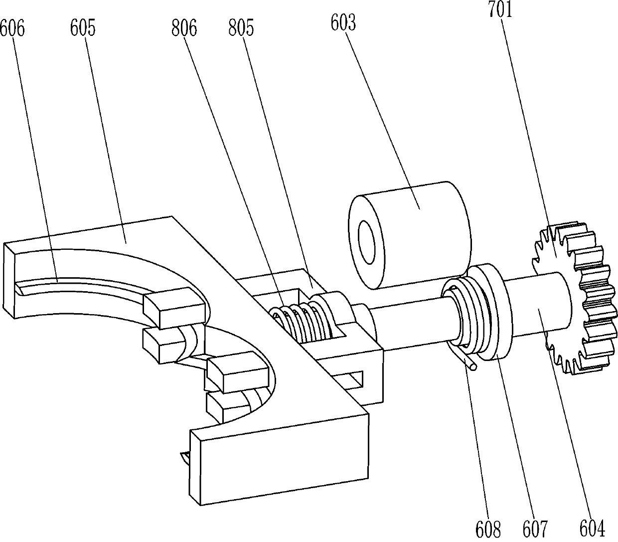
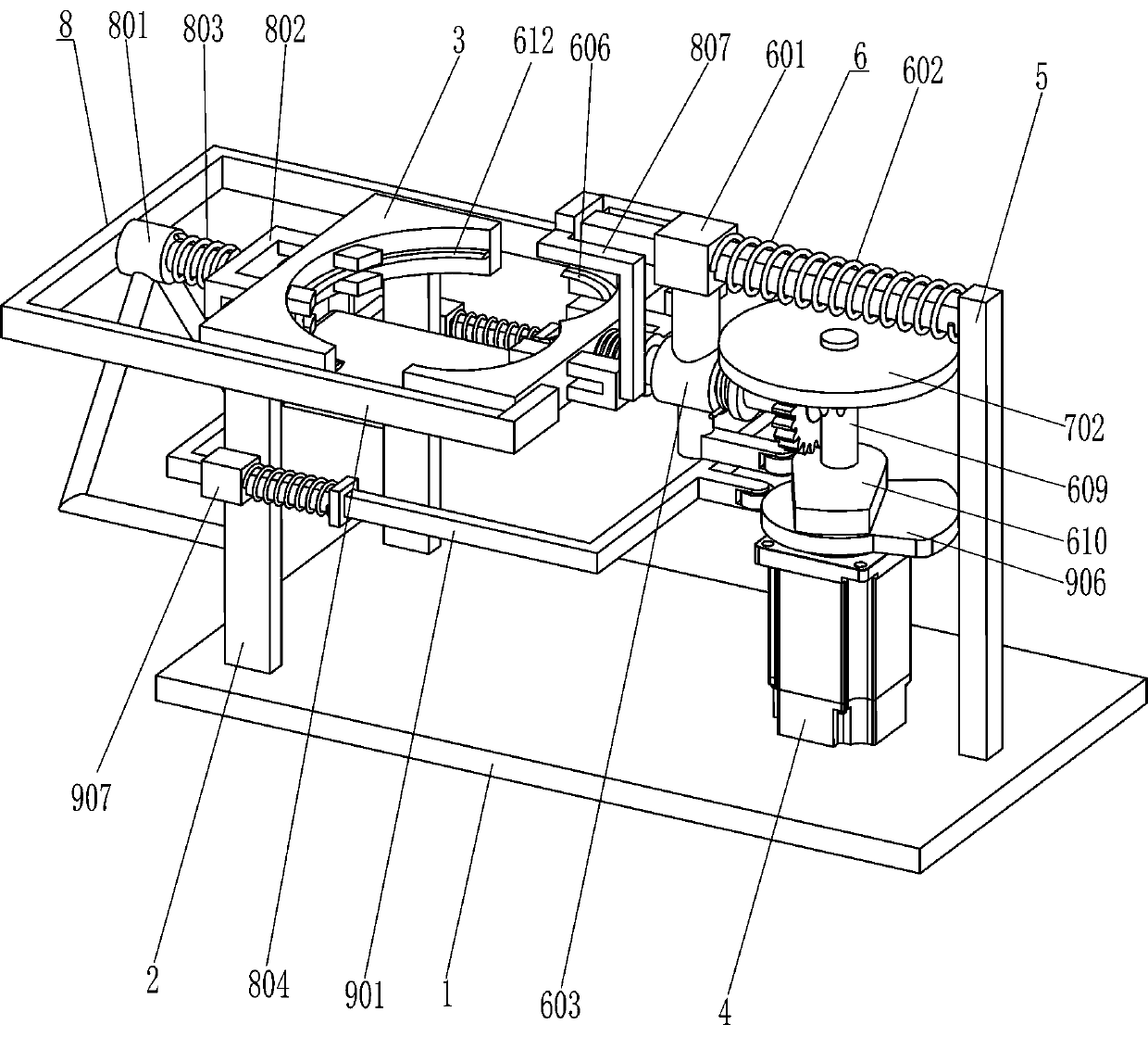
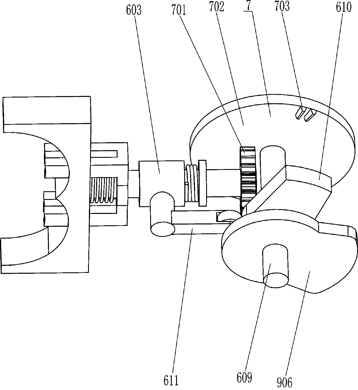
[0022] A cashew nut shelling device, such as Figure 1-3 As shown, it includes a base plate 1, a support plate 2, a first support block 3, a servo motor 4, a guide frame 5, a shell breaking assembly 6 and a rotating assembly 7. The first support block 3 is fixedly connected between the tops of the support plates 2 on both sides, the guide frame 5 is fixedly connected in the middle of the top right side of the bottom plate 1, and the servo motor 4 is installed in the middle of the top right side of the bottom plate 1 through bolt connection, and the servo motor 4 A cracking assembly 6 is provided between the output shaft of the guide frame 5 and the first support block 3, and a rotating assembly 7 is arranged on the cracking assembly 6.
[0023] The cracking assembly 6 includes a guide sleeve 601, a first spring 602, a first support sleeve 603, a first rotating shaft 604, a second supporting block 605, a first cutter 606, a fixing ring 607, a torsion spring 608, and a second ro...
Embodiment 2
[0029] On the basis of Example 1, such as figure 1 and figure 2 As shown, a discharge assembly 8 is also included, and the discharge assembly 8 includes a second support sleeve 801, a first push block 802, a second spring 803, a contact frame 804, a second push block 805, and a third spring 806 And the second contact rod 807, the front and rear sides of the left end of the guide frame 5 are fixedly connected with the second contact rod 807; The left end runs through the second support block 605 to slide and fit with it. A third spring 806 is connected between the middle part of the inner right side of the second pushing block 805 and the middle part of the outer right side of the second support block 605. The third spring 806 is sleeved on the first On the rotating shaft 604, the second pushing block 805 is in contact with the second contact rod 807, and a second support sleeve 801 is fixedly connected between the lower parts of the left side of the support plates 2 on the f...
Embodiment 3
[0032] On the basis of embodiment 1 and embodiment 2, such as figure 1 , image 3 and Figure 4 As shown, a support assembly 9 is also included, and the support assembly 9 includes a movable frame 901, a fixed block 902, a fourth spring 903, a rotating plate 904, a push block 905, a second cam 906 and a guide sleeve 907, and the first support block 3 There is a rotating plate 904 hinged in the middle of the bottom, and a guide sleeve 907 is affixed to the top of the front and rear side support plates 2 outer surfaces. A movable frame 901 is slidably arranged between the front and rear side guide sleeves 907, and the left side of the movable frame 901 is fixed in the middle. A push block 905 is connected, and the outer top of the push block 905 is in contact with the left side of the bottom of the rotating plate 904. The left parts of the front and rear sides of the movable frame 901 are fixedly connected with a fixed block 902, and the left side of the fixed block 902 is conn...
PUM
 Abstract
Description
Claims
Application Information
 - R&D
- Intellectual Property
- Life Sciences
- Materials
- Tech Scout
- Unparalleled Data Quality
- Higher Quality Content
- 60% Fewer Hallucinations
Browse by: Latest US Patents, China's latest patents, Technical Efficacy Thesaurus, Application Domain, Technology Topic, Popular Technical Reports.
© 2025 PatSnap. All rights reserved.Legal|Privacy policy|Modern Slavery Act Transparency Statement|Sitemap|About US| Contact US: help@patsnap.com


